Cloth bonding device with pressing function for cloth production
A bonding device and cloth technology, which is applied in the field of cloth bonding, can solve the problems of not being able to discharge the cloth around the cloth, reduce the use function of the device, and reduce the use effect, etc., to achieve excellent lubrication effect, reduce bottom pressure, and prevent offset Effect
- Summary
- Abstract
- Description
- Claims
- Application Information
AI Technical Summary
Problems solved by technology
Method used
Image
Examples
Embodiment 1
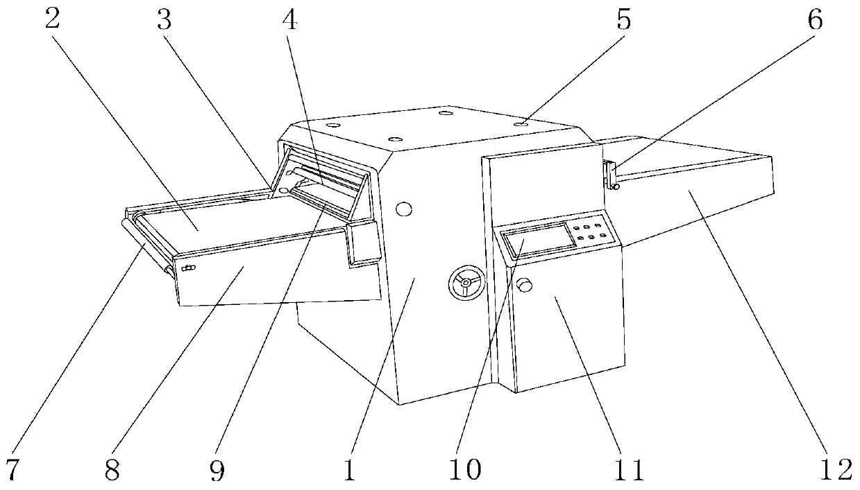
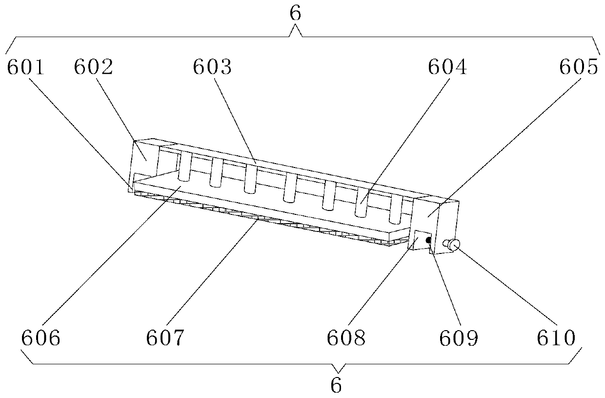
[0029] Embodiment one: if image 3 , 4As shown, the in-line fixed pressing mechanism 6 includes No. 1 straight slot 601, No. 1 positioning seat 602, support plate 603, cylinder 604, No. 2 positioning seat 605, pressing plate 606, protective pad 607, and No. 2 straight slot 608, thread groove 609, bolt 610, No. 1 straight slot 601 is located at the lower end of No. 1 positioning seat 602, support plate 603 is located at one side of No. 1 positioning seat 602, and No. 2 positioning seat 605 is located at one side of support plate 603. No. 2 straight slot 608 is located at the lower end of No. 2 positioning seat 605, thread groove 609 and bolt 610 are located inside No. 2 straight slot 608, bolt 610 is located at one side of thread groove 609, and cylinder 604 is located at the lower end of support plate 603 , the pressure plate 606 is located at the lower end of the cylinder 604, the protection pad 607 is located on the outer surface of the pressure plate 606, the lower end out...
Embodiment 2
[0030] Embodiment two: if Figure 5 As shown, the self-lubricating feed reel mechanism 7 includes a feed reel 701, a lubricating oil drip groove 702, a No. 1 mounting frame 703, an anti-skid pad 704, a rotating shaft 705, and a No. 2 mounting frame 706. The No. 1 mounting frame 703 is located at On one side of the feed reel 701, the No. 2 installation frame 706 is located on the other side of the feed reel 701, the anti-slip pad 704 is located on the outer surface of the feed reel 701, and the lubricating oil drop groove 702 is located on the No. 1 installation frame 703. At the upper end, the rotating shaft 705 is located inside the No. 2 mounting frame 706, and the outer surface of one side of the feeding reel 701 is movably connected with the inner side of the No. 2 mounting frame 706 through the rotating shaft 705. There is a Superglue, the outer wall of the feed reel 701 is fixedly connected with the inner surface of the anti-skid pad 704 through superglue, and a card slo...
Embodiment 3
[0031] Embodiment three: as Figure 6 , 7 As shown, the layered buffer type damping mechanism 9 comprises a bottom positioning plate 901, a lower spring 902, a buffer pad 903, an upper positioning plate 904, an upper spring 905, and a sponge pad 906, and the lower spring 902 is located on the outer surface of the upper end of the bottom positioning plate 901. , the buffer pad 903 is located on the upper outer surface of the lower spring 902, the upper spring 905 is located on the upper outer surface of the buffer pad 903, the sponge pad 906 is located inside the buffer pad 903, the upper positioning plate 904 is located on the upper outer surface of the upper spring 905, and the upper positioning The lower outer surface of the plate 904 is elastically connected to the upper outer surface of the buffer pad 903 through the upper spring 905, the lower outer surface of the buffer pad 903 is elastically connected to the upper outer surface of the bottom positioning plate 901 throug...
PUM
 Abstract
Description
Claims
Application Information
 - R&D
- Intellectual Property
- Life Sciences
- Materials
- Tech Scout
- Unparalleled Data Quality
- Higher Quality Content
- 60% Fewer Hallucinations
Browse by: Latest US Patents, China's latest patents, Technical Efficacy Thesaurus, Application Domain, Technology Topic, Popular Technical Reports.
© 2025 PatSnap. All rights reserved.Legal|Privacy policy|Modern Slavery Act Transparency Statement|Sitemap|About US| Contact US: help@patsnap.com


