Automatic steering bicycle
An automatic steering and bicycle technology, applied to bicycles, bicycle accessories, motor vehicles, etc., can solve the problem that bicycles cannot be ridden without letting go, and achieve the effect of ensuring safety
- Summary
- Abstract
- Description
- Claims
- Application Information
AI Technical Summary
Problems solved by technology
Method used
Image
Examples
Embodiment 1
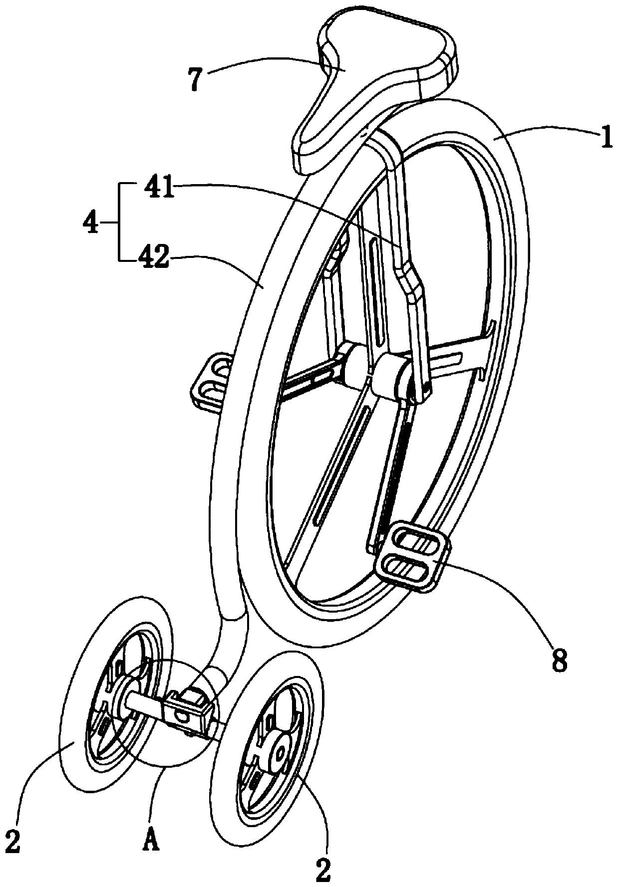
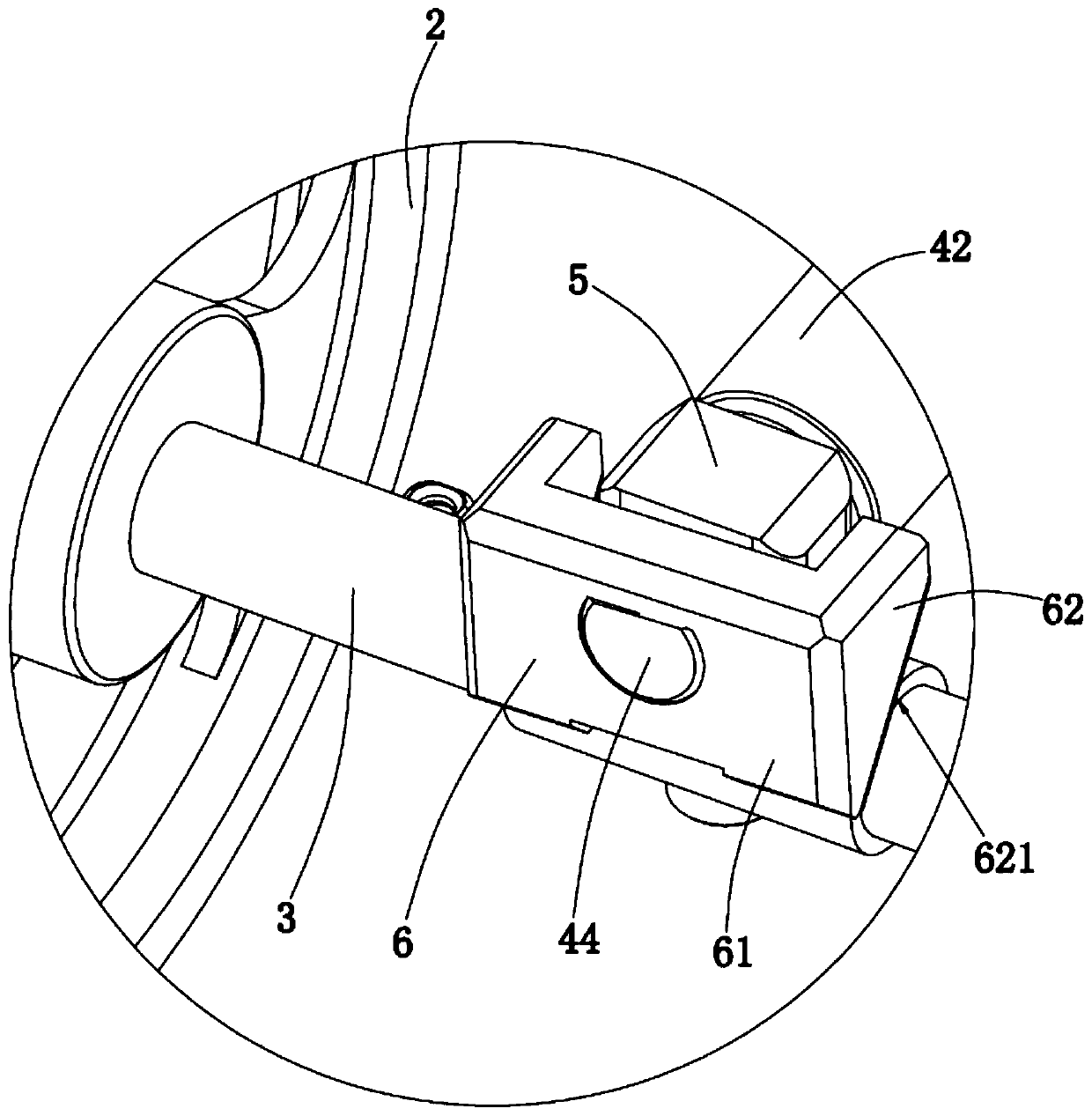
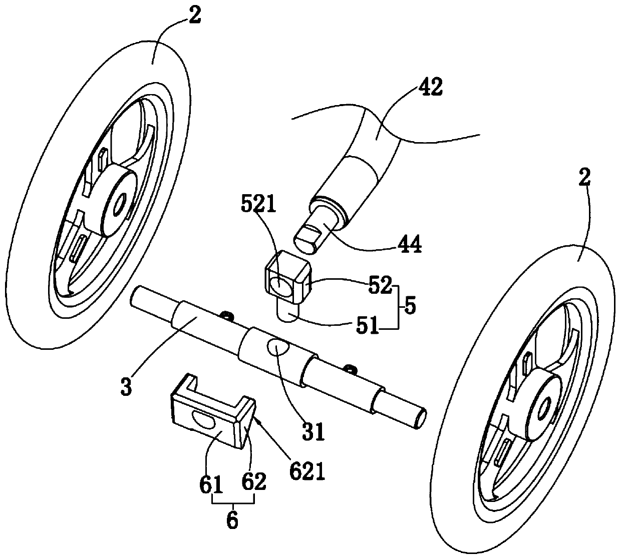
[0030] Such as Figure 1-Figure 3 As shown, a self-steering bicycle provided by the embodiment of the present invention is now described. The self-steering bicycle includes: a main shaft (not shown in the figure), a first rotating wheel 1 , a second rotating wheel 2 , a connecting shaft 3 and a main frame body 4 . Wherein, the main shaft is rotated and arranged at the center of the first rotating wheel 1, the main frame body 4 is fixed on both ends of the main shaft, there are two second rotating wheels 2, and the two second rotating wheels 2 are respectively rotated and arranged on the connecting shaft 3 The two ends of the two ends, the middle of the connecting shaft 3 and the main frame body 4 are rotatably connected by the rotating part 5, and the main frame body 4 is provided with a pusher 6 that pushes the connecting shaft 3 to turn to with the turning of the main frame body 4.
[0031] In this embodiment, the self-steering bicycle also includes a pedal mechanism 8, whi...
Embodiment 2
[0041] The difference between this embodiment and Embodiment 1 is that: the structure of the main frame body 40 in this embodiment is different from the structure of the main frame body 4 in Embodiment 1. The specific structure of the main frame body 4 will be described below.
[0042] Such as Figure 4 and Figure 5 As shown, in this embodiment, the main frame body 40 includes: a first U-shaped frame body 41 and a second U-shaped frame body 43, and the second U-shaped frame body 43 is horizontally arranged and fixed on both ends of the main shaft, so that The first rotating wheel 1 can be rolled relative to the second U-shaped frame body 43, the first U-shaped frame body 41 is vertically arranged on the second U-shaped frame body 43, and the first U-shaped frame body 41 is provided with a vehicle Seat 7, vehicle seat 7 is used for being taken by people, and the pedal mechanism 8 of making things convenient for people's feet, realizes the motion of bicycle. The second U-sha...
Embodiment 3
[0044] The difference between the present embodiment and the second embodiment is that the structures of the connecting shaft 30 , the rotating member 50 and the pushing member 60 in this embodiment are different from those of the connecting shaft 3 , the rotating member 5 and the pushing member 6 in the second embodiment. The specific structure of the main frame body 40 will be described below.
[0045] Such as Figure 6 and Figure 7 As shown, in this embodiment, the main frame body 40 includes a first U-shaped frame body 41 and a second U-shaped frame body 43, and the second U-shaped frame body 43 is horizontally arranged and fixed on both ends of the main shaft, so that the first U-shaped frame body 43 A rotating wheel 1 can roll and travel relative to the second U-shaped frame body 43, the first U-shaped frame body 41 is vertically arranged on the second U-shaped frame body 43, and the first U-shaped frame body 41 is provided with a vehicle seat 7 , the vehicle seat 7 i...
PUM
 Abstract
Description
Claims
Application Information
 - R&D
- Intellectual Property
- Life Sciences
- Materials
- Tech Scout
- Unparalleled Data Quality
- Higher Quality Content
- 60% Fewer Hallucinations
Browse by: Latest US Patents, China's latest patents, Technical Efficacy Thesaurus, Application Domain, Technology Topic, Popular Technical Reports.
© 2025 PatSnap. All rights reserved.Legal|Privacy policy|Modern Slavery Act Transparency Statement|Sitemap|About US| Contact US: help@patsnap.com


