Steam parameter increase based synergistic gas power generation system and method

A technology of power generation system and steam parameters, which is applied in the steam generation method using pressure combustion, steam generation, separation method, etc., can solve the problems of low thermal efficiency, high heat consumption, low efficiency, etc., and achieve thermal efficiency improvement, increase flexibility, The effect of avoiding energy loss problems

Active Publication Date: 2018-08-24
HUATIAN NANJING ENG & TECH CORP MCC
View PDF4 Cites 0 Cited by
  • Summary
  • Abstract
  • Description
  • Claims
  • Application Information

AI Technical Summary

Problems solved by technology

However, both low-parameter boilers and low-parameter steam turbines have disadvantages such as low efficiency and high heat consumption, which leads to the underutilization of by-product gas resources in the factory
For example, a steel plant has successively built more than ten medium-temperature and medium-pressure steam turbines, and the steam is supplied by multiple medium-temperature and medium-pressure gas boilers. The actual operating efficiency of these medium-temperature, medium-pressure and small-capacity boilers is only 82%, which is far lower than that of high-parameter large-capacity boilers. In addition, the efficiency of medium-temperature and medium-pressure steam turbines is much lower than that of high-parameter steam turbines, which leads to low thermal efficiency of the whole plant and a serious shortage of thermal energy utilization of by-product gas
For this reason, relevant technical personnel have been looking for an effective transformation method to improve the overall thermal efficiency of the unit. However, since the industrial traction steam turbine supplies energy for the core upstream process equipment, it must ensure its safe and stable operation, which is obviously different from the conventional Unit modification

Method used


Image

  • Steam parameter increase based synergistic gas power generation system and method

Examples


Embodiment Construction

[0021] In the following description, for purposes of explanation, numerous specific details are set forth in order to provide a thorough understanding of one or more embodiments. It may be evident, however, that these embodiments may be practiced without these specific details.

[0022] Various embodiments according to the present invention will be described in detail below with reference to the accompanying drawings.

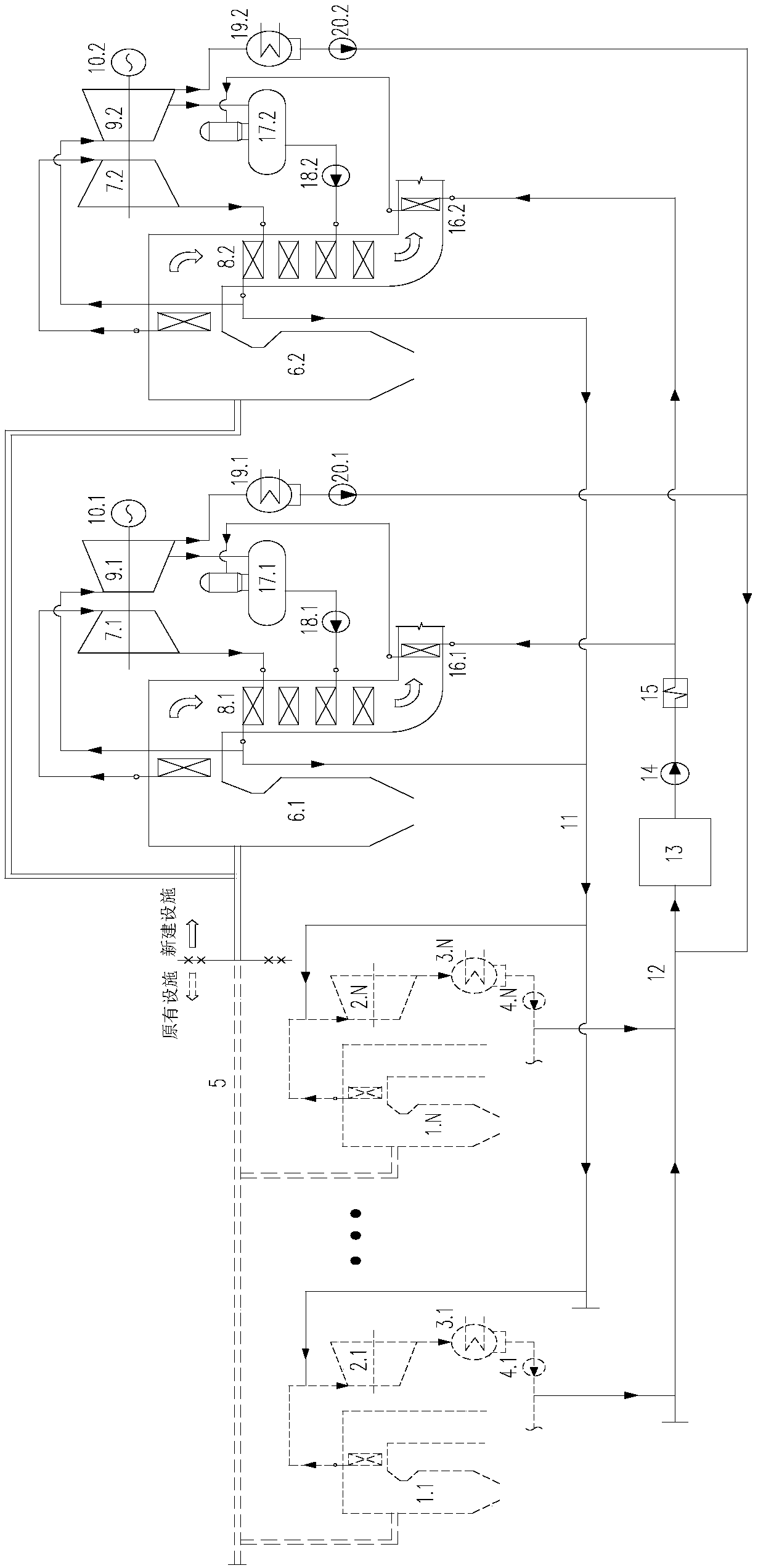
[0023] figure 1 It is a schematic diagram of the gas-stimulated power generation system based on steam parameter promotion in the present invention, such as figure 1 As shown, the gas power generation efficiency enhancement system based on steam parameter improvement includes a new power generation system and an original power system,

[0024] The newly-built power generation system includes at least one newly-built gas generating unit, and the newly-built gas generating unit includes a newly-built gas boiler 6, a newly-built first steam turbine 7, a newly-buil...


PUM


Abstract

The invention provides a steam parameter increase based synergistic gas power generation system and method. The system comprises a new generation system and an original power system which intercommunicate, wherein the new generation system comprises a new gas boiler, a new first steam turbine, a new second steam turbine, a new generator, a reheater and a deaerator; the original power system comprises an original gas boiler and an original steam turbine; the new gas boiler communicates with the original gas boiler through a gas pipeline network; a steam outlet of the new gas boiler communicateswith a steam inlet of the new first steam turbine; a steam exhausting port of the new first steam turbine communicates with a steam inlet of the reheater; a steam outlet of the reheater communicateswith steam inlets of the original steam turbine and the new second steam turbine; the new second steam turbine is provided with a steam pumping port which communicates with a steam inlet of the deaerator; the new first steam turbine is a backpressure type steam turbine; the new second steam turbine is a steam condensing type steam turbine; and the new first steam turbine is coaxially connected tothe new second steam turbine to drive the new generator together to generate power.

Description

technical field [0001] The invention relates to the technical field of efficient energy utilization, in particular to a gas efficiency-enhancing power generation system and method based on steam parameter improvement. Background technique [0002] In the production process of iron and steel, coking and other fields, there are a large number of high-power and high-energy-consumption rotating machinery, including fans, compressors, water pumps, etc., as auxiliary facilities for process equipment, these rotating machinery lead to the high power consumption rate of enterprises. main factor. On the other hand, by-product gas, such as blast furnace gas, converter gas, coke oven gas, etc., will be produced in the process of iron and steel and coking production. In recent years, with the improvement of awareness of energy conservation and emission reduction in various factories and the improvement of technical capabilities, a large number of factories have adopted steam turbine dri...

Claims


Application Information

Patent Timeline
Patent Type & Authority Applications(China)
IPC IPC(8): F22B1/22F22D1/32F22D1/50F22D11/06F23K5/00F01D15/10F01K11/02
Inventor 江文豪
Owner HUATIAN NANJING ENG & TECH CORP MCC
Why Eureka
Try Eureka