Automatic steering bicycle

An automatic steering and bicycle technology, which is applied to bicycles, bicycle accessories, motor vehicles, etc., can solve the problem that bicycles cannot be ridden without letting go, and achieve the effect of ensuring coordination

Pending Publication Date: 2020-04-17
六壹八技术(深圳)有限公司
View PDF0 Cites 1 Cited by
  • Summary
  • Abstract
  • Description
  • Claims
  • Application Information

AI Technical Summary

Problems solved by technology

[0003] The purpose of the present invention is to provide an automatic steering bicycle, aiming to solve the technical problem in the prior art that the bicycle cannot be ridden with hands free for ordinary cyclists

Method used


Image

  • Automatic steering bicycle
  • Automatic steering bicycle
  • Automatic steering bicycle

Examples


Embodiment 1

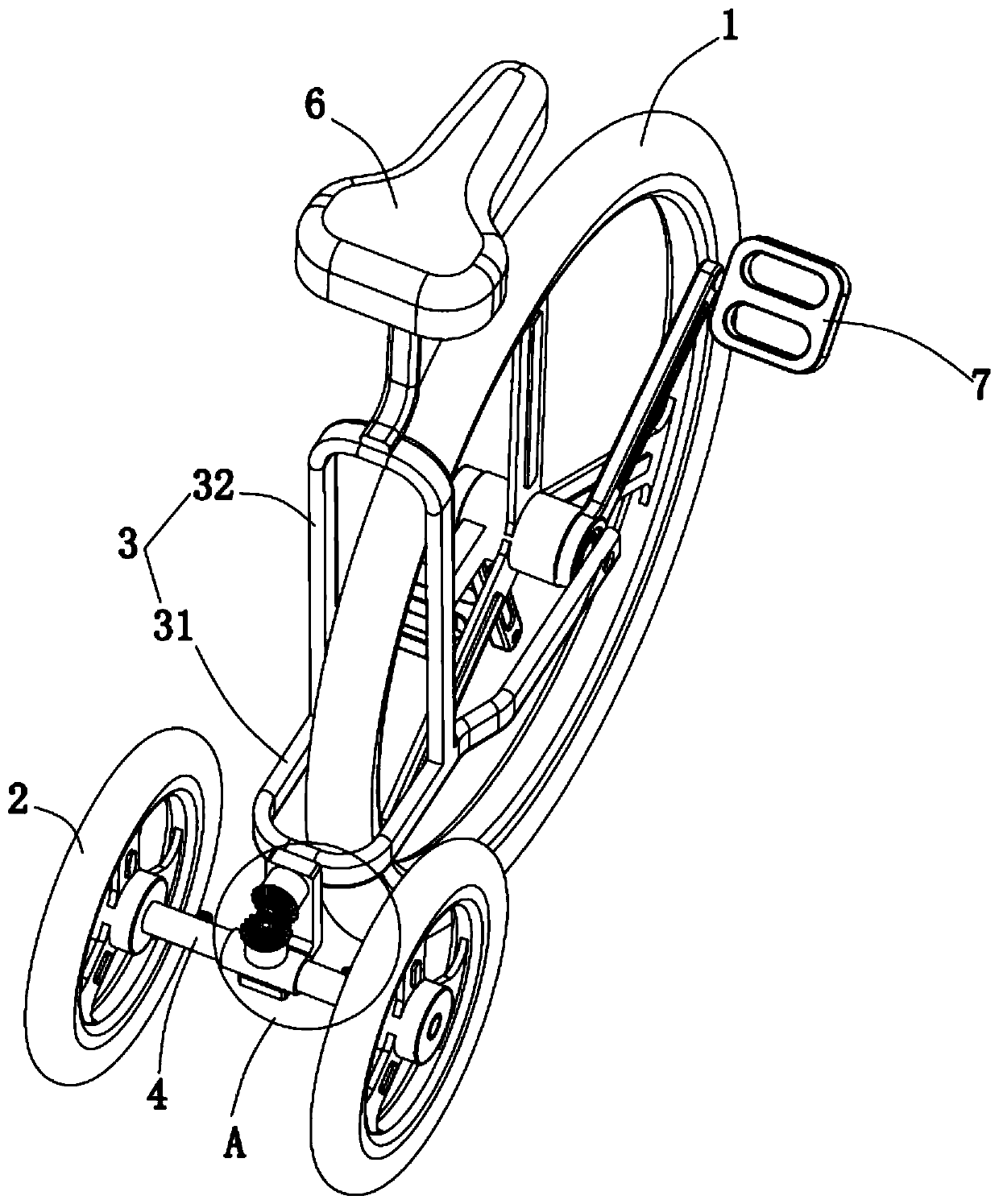
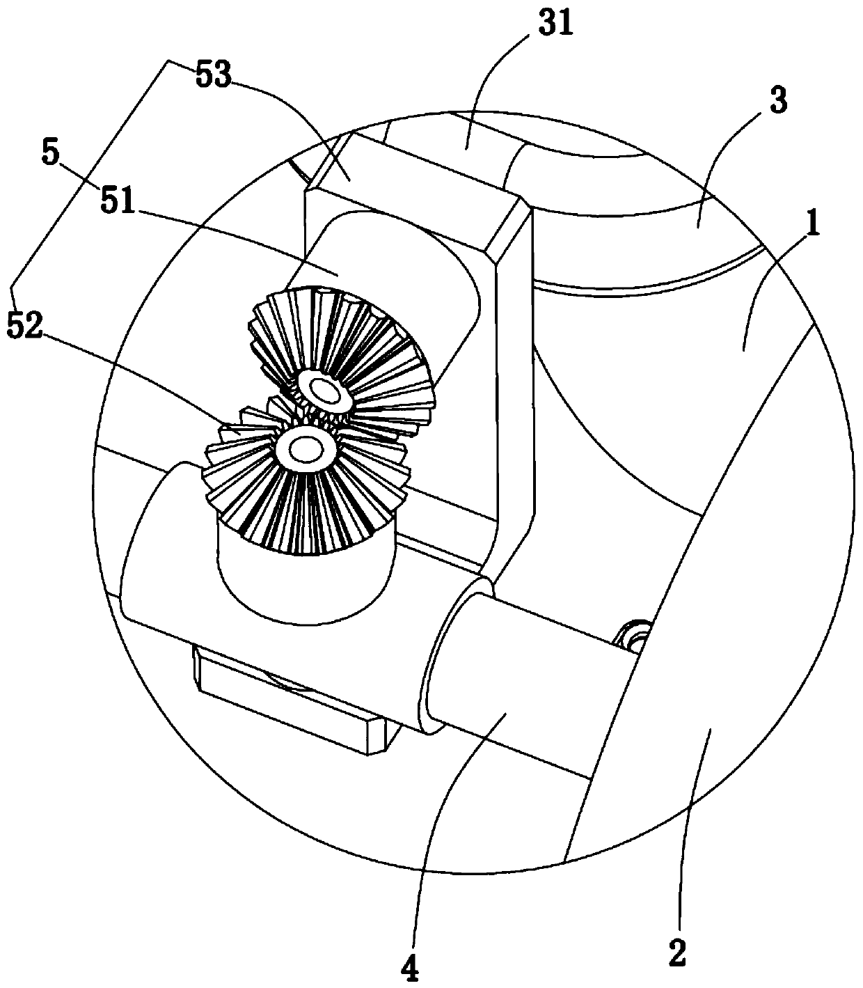
[0029] Such as Figure 1-Figure 3 As shown, the embodiment of the present invention provides an automatic steering bicycle, which includes: a main shaft (not shown in the figure), a first rotating wheel 1, a second rotating wheel 2, a main frame body 3 and a connecting shaft 4, The main shaft rotates and is arranged at the center of the first rotating wheel 1, the main frame body 3 is fixed on the two ends of the main shaft, the second rotating wheel 2 is provided with two, and the two second rotating wheels 2 are respectively rotated on two sides of the connecting shaft 4. end, the middle of the connecting shaft 4 is rotationally connected with the main frame body 3, and an engaging mechanism 5 is also provided between the connecting shaft 4 and the main frame body 3, and the engaging mechanism 5 is used to cooperate with the main frame body 3 to limit or drive the second rotating wheel 2 changes direction. In this embodiment, the first rotating wheel 1 is a front wheel, and...

Embodiment 2

[0040] In this embodiment, the difference from other embodiments lies in the specific structures of the connecting shaft 4 and the engaging mechanism 5 , and the specific structures of the connecting shaft 4 and the engaging mechanism 5 will be described in detail below.

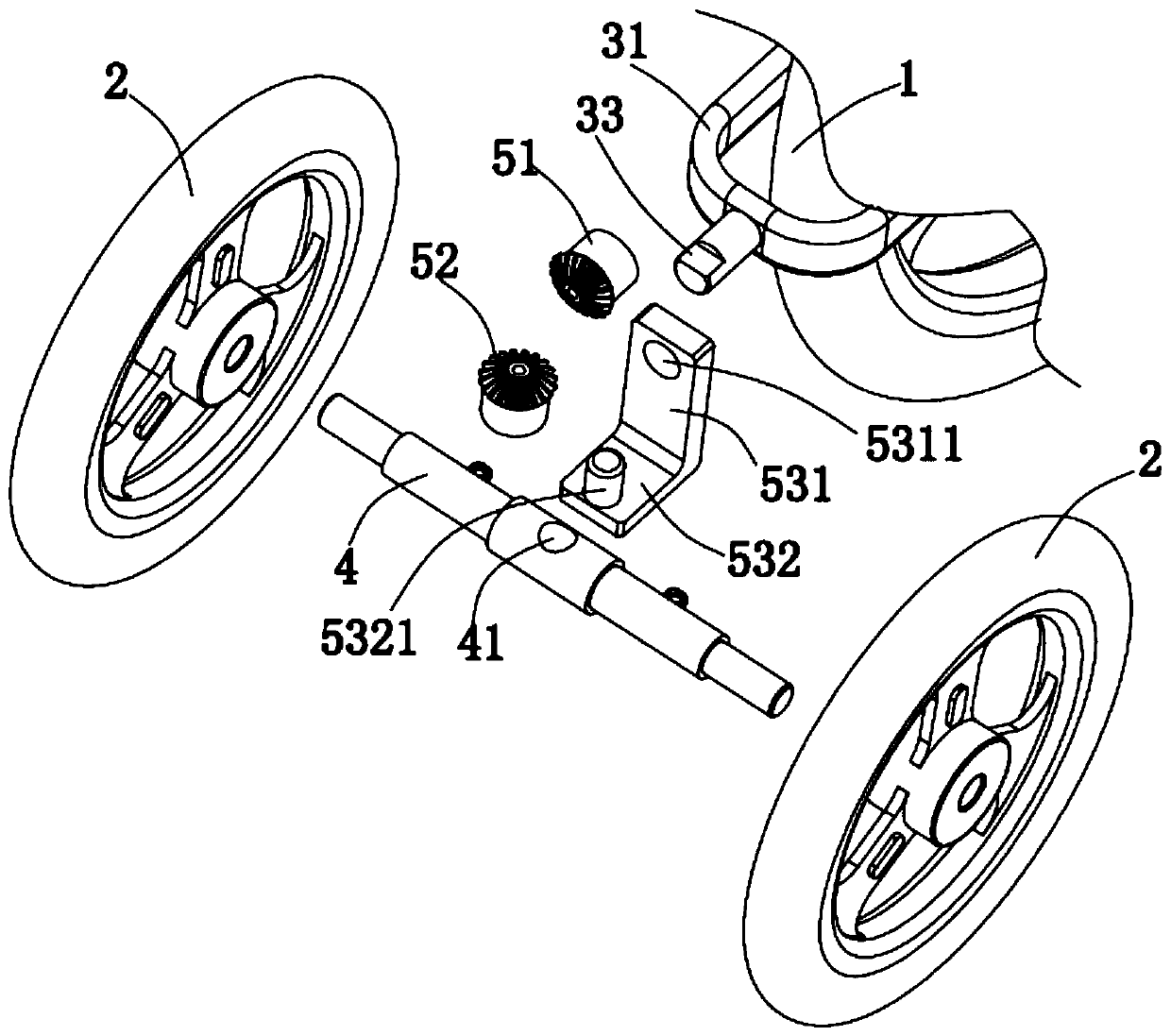
[0041] Such as Figure 4-Figure 6 As shown, the connecting shaft 4 includes: a middle section 42, and a first installation section 43 and a second installation section 44 respectively hinged to both ends of the middle section 42, wherein a second rotating wheel 2 is rotatably mounted on the first installation section 43 On the top, another second rotating wheel 2 is rotatably mounted on the second mounting section 44 . In this way, the second rotating wheel 2 can yaw left and right relative to the middle section 42 , preparing for synchronous yaw following the first rotatable wheel 1 .

[0042] Such as Figure 4-Figure 6 As shown, the engagement mechanism 5 includes: a rack 54 arranged parallel to the midd...


PUM


Abstract

The invention, which relates to the technical field of bicycles, provides an automatic steering bicycle comprising a main shaft, a first rotating wheel, second rotating wheels, a main frame body and aconnecting shaft. The main shaft is rotationally arranged in the center of the first rotating wheel; the main frame body is fixed to the two ends of the main shaft; the two second rotating wheels arerotationally arranged at the two ends of the connecting shaft respectively; the connecting shaft is rotationally connected with the main frame body; and a meshing mechanism for limiting or driving the second rotating wheels to be changed by cooperating with the main frame body is arranged between the connecting shaft and the main frame body. The first rotating wheel and the two second rotating wheels form a tricycle and thus the bicycle has balance and does not turn over, so that the balance of the bicycle does not need to be controlled by hands; meanwhile, the direction of the bicycle can bechanged by changing the advancing direction of the first rotating wheel, the advancing direction of the first rotating wheel can be achieved by deviating the human body, so that the bicycle can be ridden by loosening the hands.

Description

technical field [0001] The invention relates to the technical field of bicycles, in particular to an automatic steering bicycle. Background technique [0002] Bicycle is a traditional industry with a history of more than 100 years. Due to environmental protection and traffic problems, bicycles have gradually become everyone's favorite means of transportation. Bicycles generally include two-wheeled bicycles, three-wheeled bicycles and four-wheeled bicycles at present. Existing bicycle generally all comprises vehicle frame, front wheel support, front wheel, rear wheel and chain sprocket driving mechanism, and front wheel rotation is arranged on the front wheel support, and rear wheel rotation is arranged on vehicle frame, and one end of vehicle frame passes through The rotating connection structure is sleeved on the support so as to realize the steering connection of the front wheel relative to the rear wheel. The front wheel support is also provided with a handle, which is u...

Claims


Application Information

Patent Timeline
Patent Type & Authority Applications(China)
IPC IPC(8): B62K5/027B62K5/08B62K21/00
CPCB62K5/027B62K5/08B62K21/00
Inventor 夏正磊王琴龙美秀李鑫
Owner 六壹八技术(深圳)有限公司
Why Eureka
Try Eureka