
Full-automatic winding facility

A fully automatic and equipment technology, applied in the direction of winding strips, labels, packaging, etc., can solve the problems of cumbersome disassembly and assembly, cumbersome operation process, reducing production efficiency and so on

Pending Publication Date: 2020-04-17
瑞安市德冠机械有限公司
View PDF1 Cites 4 Cited by
  • Summary
  • Abstract
  • Description
  • Claims
  • Application Information

AI Technical Summary

Problems solved by technology

As a result, the swing angle of the upper cutter with the upper swing arm towards the pre-cutting station needs to be fine-tuned to varying degrees
At present, the upper knife device can only be replaced by changing a different type of upper knife device or adjusting the driving stroke of the power source 1 that drives the upper swing arm. Not only the operation process is cumbersome, but also the whole machine needs to be adjusted again after replacement. , it takes a lot of manpower and material resources, which directly reduces the production efficiency and increases the labor cost
Adjusting the driving stroke of its power source 1 requires professional adjustment operators to carry out the operation, which is cumbersome to disassemble and assemble, and consumes manpower and material resources

Method used


Image

  • Full-automatic winding facility
  • Full-automatic winding facility
  • Full-automatic winding facility

Examples


Embodiment Construction

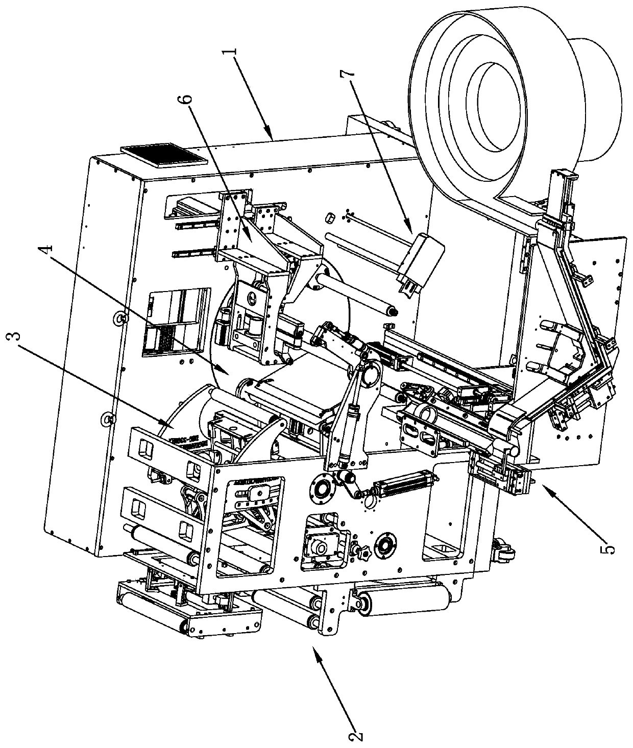
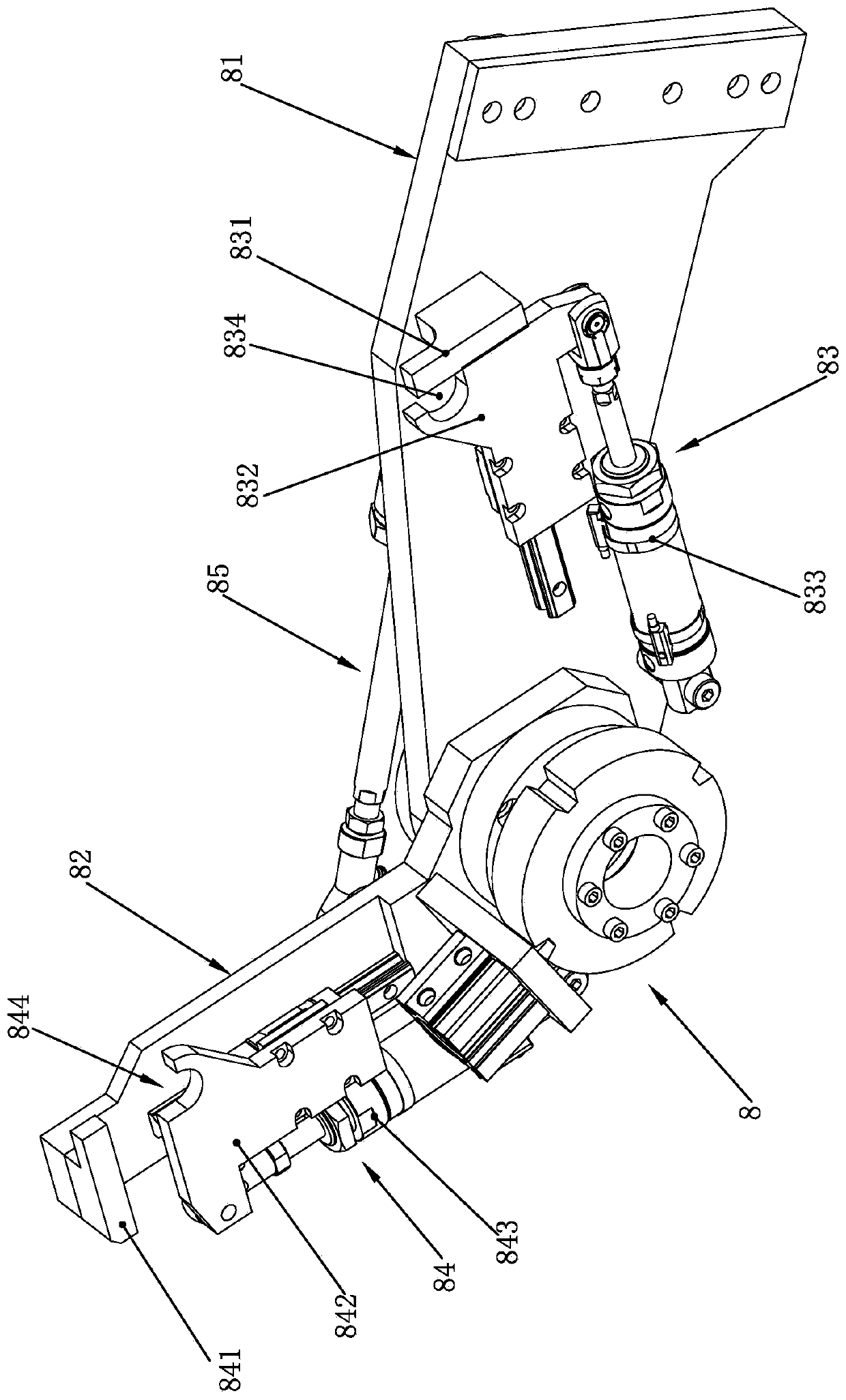
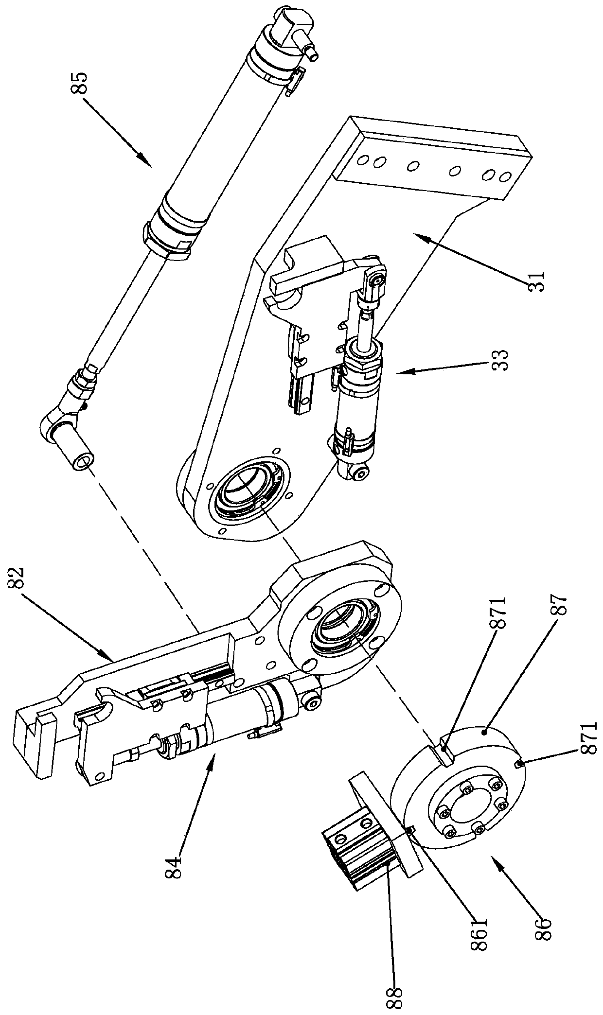
[0034] Such as figure 1 — Figure 12 A kind of fully automatic winding equipment shown, comprises frame 1, is located at the feeding device 2 on frame 1, cutting device 3, rewinding device 4, paper feeding pipe core device 5, labeling device 6 and The finished product output device 7, the winding device 4 includes a turntable 42 that is driven by the drive source and the main drive shaft 41 and can rotate in the circumferential direction. The drive source can be a motor. Rolling station 422, labeling station 423 and finished product output station 424. The turntable 42 is provided with a number of rewinding air shafts 43 that can run to each station along with the turntable 42. The cutting device 3 includes a knife mechanism. 31. The lower knife mechanism 32 corresponding to the upper knife mechanism 31 and the paper pressing mechanism 33 located at the upper knife mechanism 31, there is a pre-cutting station 34 between the upper knife mechanism 31 and the lower knife mechani...


PUM


Abstract

The invention relates to a full-automatic winding facility. The following technical scheme is provided. The full-automatic winding facility comprises a machine frame, a feeding device, a cutting device, a winding device, a paper tube core conveying device, a labelling device and a finished product output device. The feeding device, the cutting device, the winding device, the paper tube core conveying device, the labelling device and the finished product output device are arranged on the machine frame. The winding device comprises a rotating disc. The rotating disc can rotate in the circumferential direction. Multiple winding air expansion shafts which can run along with the rotating disc are arranged on the rotating disc. The cutting device comprises an upper cutter mechanism, a lower cutter mechanism and a paper press mechanism. The lower cutter mechanism and the upper cutter mechanism are correspondingly arranged, and the paper press mechanism is located on the upper cutter mechanism. A winding auxiliary clamping device is arranged between the winding device and the cutting device. Adjusting wallboards which are symmetrically arranged in pairs, are erected on the machine frame and enable the upper cutter mechanism to be integrated are arranged on the upper cutter mechanism. By the adoption of the technical scheme, the full-automatic winding facility which can adjust the cutting distance according to winding drums with different thicknesses, prevents the winding air expansion shafts against bending deformation in the machining process, is stable in clamping and supportingmovement and improves the winding efficiency is provided.

Description

technical field [0001] The invention relates to a fully automatic winding device. Background technique [0002] Supermarket cash register paper and label paper are mainly realized by automatic winding equipment. This type of equipment is mainly composed of feeding device, winding device, cutting device, paper feeding die device, labeling device and finished product output device. [0003] Among them, the traditional winding device is a rotatable turntable. On the circumferential end surface of the turntable, there are upper tube core station, winding station, labeling station and finished product output station. And the rewinding air-expanding shaft at each station can be rotated with the turntable. When one of the rewinding inflatable shafts enters the rewinding station through the upper tube core station, the winding equipment will set the paper roll outside the tube core on the rewinding inflatable shaft, and the rewinding inflatable shaft When the rewinding is complete...

Claims


Application Information

Patent Timeline
IPC IPC(8): B65H18/02B65H18/10B65H19/26B65H19/30B65C3/00B65C9/30
CPCB65C3/00B65C9/30B65H18/02B65H18/021B65H18/10B65H19/26B65H19/30B65H2701/192
Inventor 钟学张强
Owner 瑞安市德冠机械有限公司
Learn More