A self-centering yarn drum positioning device for twisting machine

An automatic centering and positioning device technology, applied in the field of textile fabrics, can solve the problems of wire breakage, increase the friction between the wire and the pay-off drum, and affect the spinning efficiency, so as to facilitate installation and taking, avoid wire wear, and avoid The effect of wire knotting

Active Publication Date: 2021-02-05
南通鑫唐纺织印染有限公司
View PDF9 Cites 0 Cited by
  • Summary
  • Abstract
  • Description
  • Claims
  • Application Information

AI Technical Summary

Problems solved by technology

[0003] In the prior art, when twisting, most of the pay-off cylinders are placed vertically on the twisting machine, but in this way, the pay-off cylinders will rub against the pay-off cylinders when the wires are unwound, which will easily cause the wires to break. Damage, and usually the pay-off drum is clamped by the bottom clamping device, but it will still vibrate due to centrifugal force during rotation, and the fixation is not firm, causing the pay-off drum to break away from the fixing device, thereby affecting the twisting efficiency, and in During the fixing process, because there is no centering device, the centering of the pay-off cylinder is not accurate, which may easily lead to the deviation of the axis, so that it is easy to vibrate due to eccentricity during the rotation process, which will affect the spinning efficiency and further increase the cost of the wire and pay-off. The friction of the barrel will increase the damage of the wire and affect the quality of the wire. At the same time, the pay-off drum that vibrates due to eccentricity will also easily cause knotting of the wire, which will easily cause the wire to break and affect the twisting efficiency. In addition, the existing twisting The machine pay-off device has no fixing device, which causes the pay-off drum to shake due to no fixing device during installation and taking, which increases the difficulty of installing and taking the pay-off drum.

Method used


Image

  • A self-centering yarn drum positioning device for twisting machine
  • A self-centering yarn drum positioning device for twisting machine
  • A self-centering yarn drum positioning device for twisting machine

Examples


Embodiment Construction

[0029] The following will clearly and completely describe the technical solutions in the embodiments of the present invention with reference to the accompanying drawings in the embodiments of the present invention. Obviously, the described embodiments are only some, not all, embodiments of the present invention. Based on the embodiments of the present invention, all other embodiments obtained by persons of ordinary skill in the art without making creative efforts belong to the protection scope of the present invention.

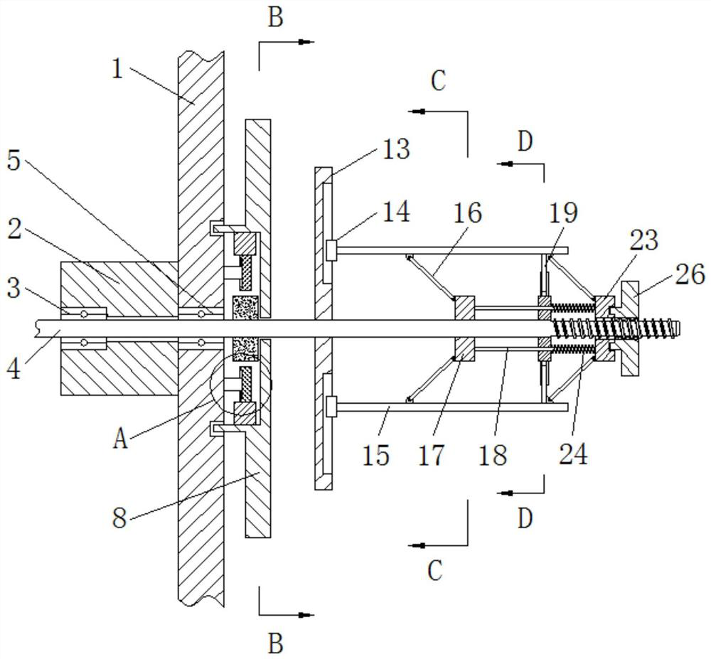
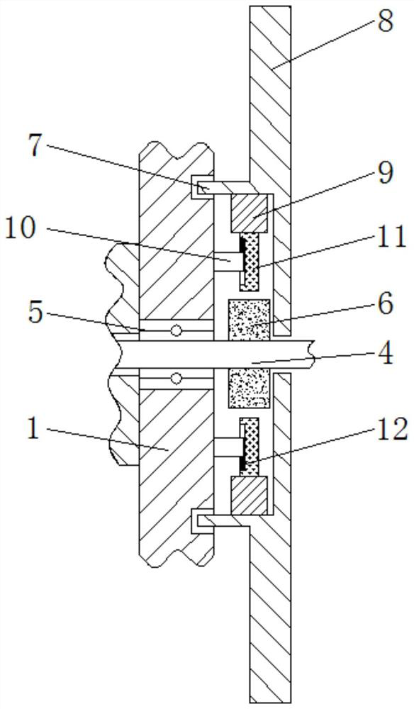
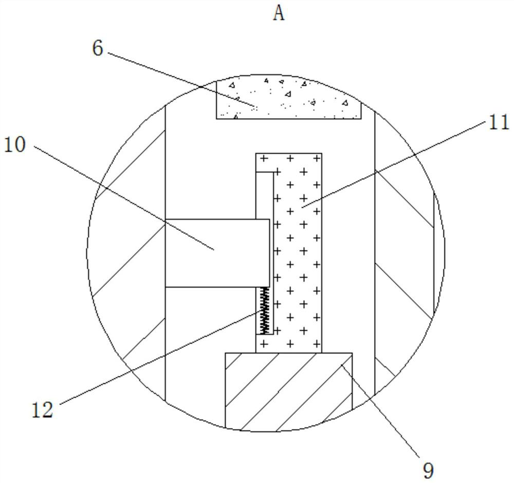
[0030] see Figure 1-8 , an automatic centering yarn drum positioning device for a twisting machine, comprising a twisting machine body 1, a fixed shaft sleeve 2, a first bearing 3, a rotating shaft 4, a second bearing 5, a brake disc 6, and a brake ring 7 , brake runner 8, bump 9, fixed block 10, brake slider 11, return spring 12, positioning ring 13, positioning slider 14, positioning rod 15, first push rod 16, first push ring 17, Connecting rod 18, telesco...


PUM


Abstract

The invention relates to the technical field of textile fabrics, and discloses an automatic centering yarn drum positioning device for a twisting machine, which includes a twisting machine body, and a fixed shaft sleeve is fixedly connected to the outside of the twisting machine body. The inside of the shaft sleeve is fixedly connected with a first bearing; The outside of the brake ring is connected with a brake ring, the outside of the brake ring is fixedly connected with a brake runner, the inside of the brake ring is fixedly connected with a bump, and the outside of the twisting machine body is fixedly connected with a fixed block, The outside of the fixed block is slidably connected with a brake slider. Through the cooperation of the rotating shaft and the positioning rod, the vertically fixed pay-off barrel becomes a horizontally fixed pay-off barrel, which avoids reducing the friction between the wire and the pay-off barrel, and avoids the occurrence of wire rods. damage, to ensure the quality of the wire.

Description

technical field [0001] The invention relates to the technical field of textile fabrics, in particular to an automatic centering yarn drum positioning device for a twisting machine. Background technique [0002] In the fabric weaving process, it is usually necessary to twist the textile yarn in advance, and the twisting machine is a textile machinery equipment that twists multiple strands of spun yarn into one strand, and its function is to process the yarn or the combined strand yarn product into a linear shape. Products, thread for weaving and knitting, including twisting machine body and circuit part, the spindle outside the twisting machine body is connected with the motor output shaft of the circuit part, and the front end of the spindle is equipped with a connecting piece corresponding to the tap switch. [0003] In the prior art, when twisting, most of the pay-off cylinders are placed vertically on the twisting machine, but in this way, the pay-off cylinders will rub a...

Claims


Application Information

Patent Timeline
Patent Type & Authority Patents(China)
IPC IPC(8): D01H1/18D01H1/20
CPCD01H1/18D01H1/20
Inventor 郑明约
Owner 南通鑫唐纺织印染有限公司
Why Eureka
Try Eureka