
An automatic tile cement mortar applicator for building construction

A technology of building construction and cement mortar, which is applied in the direction of construction and building construction, etc., can solve the problems of uneven application and low work efficiency, and achieve the effect of avoiding falling off and high work efficiency

Active Publication Date: 2021-06-08
李乃元
View PDF6 Cites 0 Cited by
  • Summary
  • Abstract
  • Description
  • Claims
  • Application Information

AI Technical Summary

Problems solved by technology

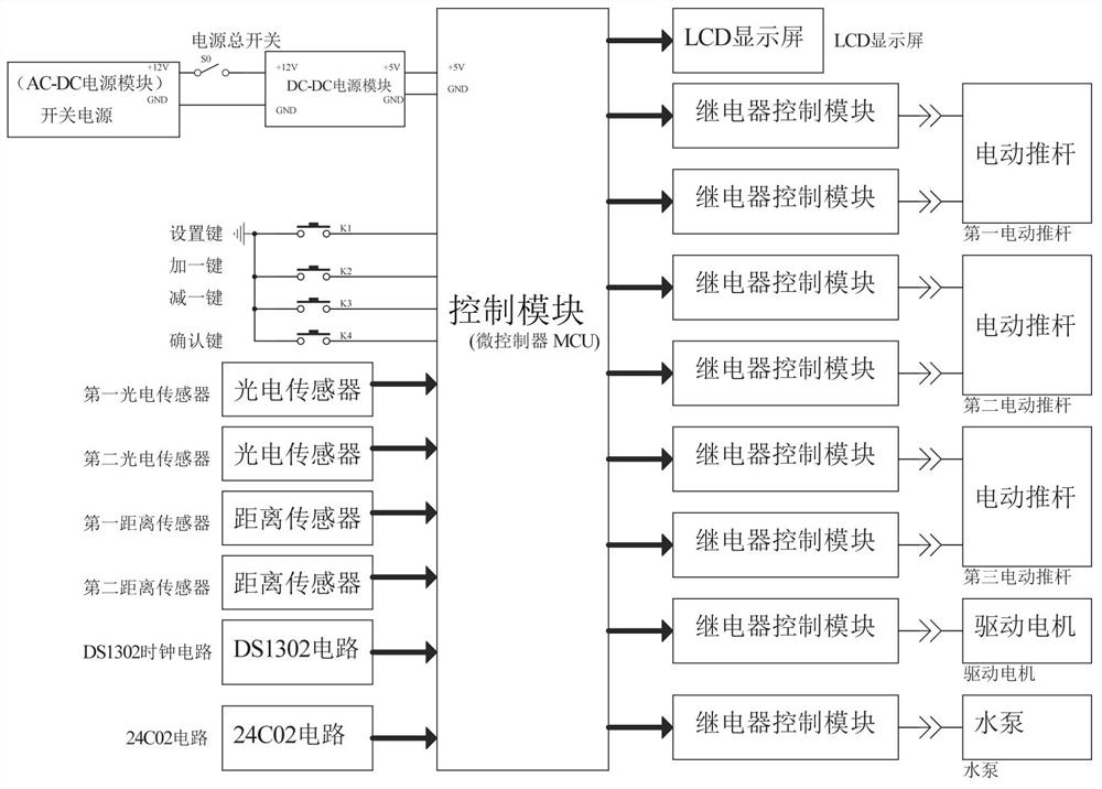
[0005] In order to overcome the shortcomings of construction workers applying cement mortar on tiles with a trowel, the work efficiency is low and the application is not uniform enough, the technical problem of the present invention is to provide a kind of automatic tile cement mortar for building construction with high work efficiency and uniform application Applicator

Method used


Image

  • An automatic tile cement mortar applicator for building construction
  • An automatic tile cement mortar applicator for building construction
  • An automatic tile cement mortar applicator for building construction

Examples


Embodiment 1

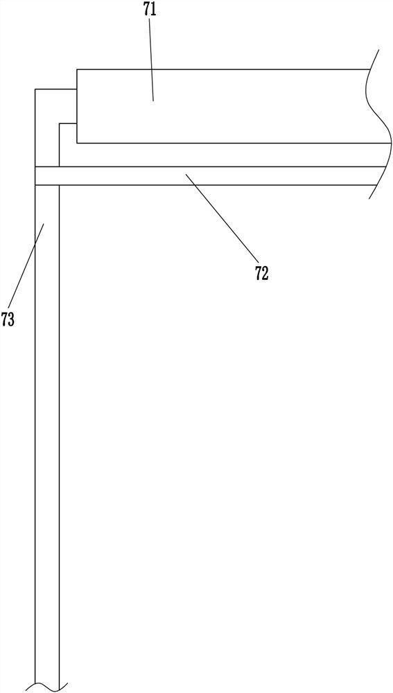
[0025] An automatic tile cement mortar applicator for building construction, see figure 1 and image 3 , including a mounting frame 1, a blocking rod 2, a cross bar 6, a pulling device 7, a lifting device 8, a pillar 9, a lower hopper 10, a discharge pipe 11, an elastic sleeve 12 and a smearing pipe 13, and the left side of the mounting frame 1 is fixed The stop rod 2 is connected, the installation frame 1 is connected with the stop rod 2 by welding, the top right side of the installation frame 1 is connected with the cross bar 6, the installation frame 1 is connected with the cross bar 6 by welding, and the top of the cross bar 6 There is a pulling device 7, the pulling device 7 is used to pull the tiles, the top left side of the installation frame 1 is provided with a lifting device 8, the lifting device 8 is used to transport the tiles, the upper part of the installation frame 1 is fixed with a pillar 9, and the lower hopper 10 is installed on the pillar 9 the top, the low...

Embodiment 2

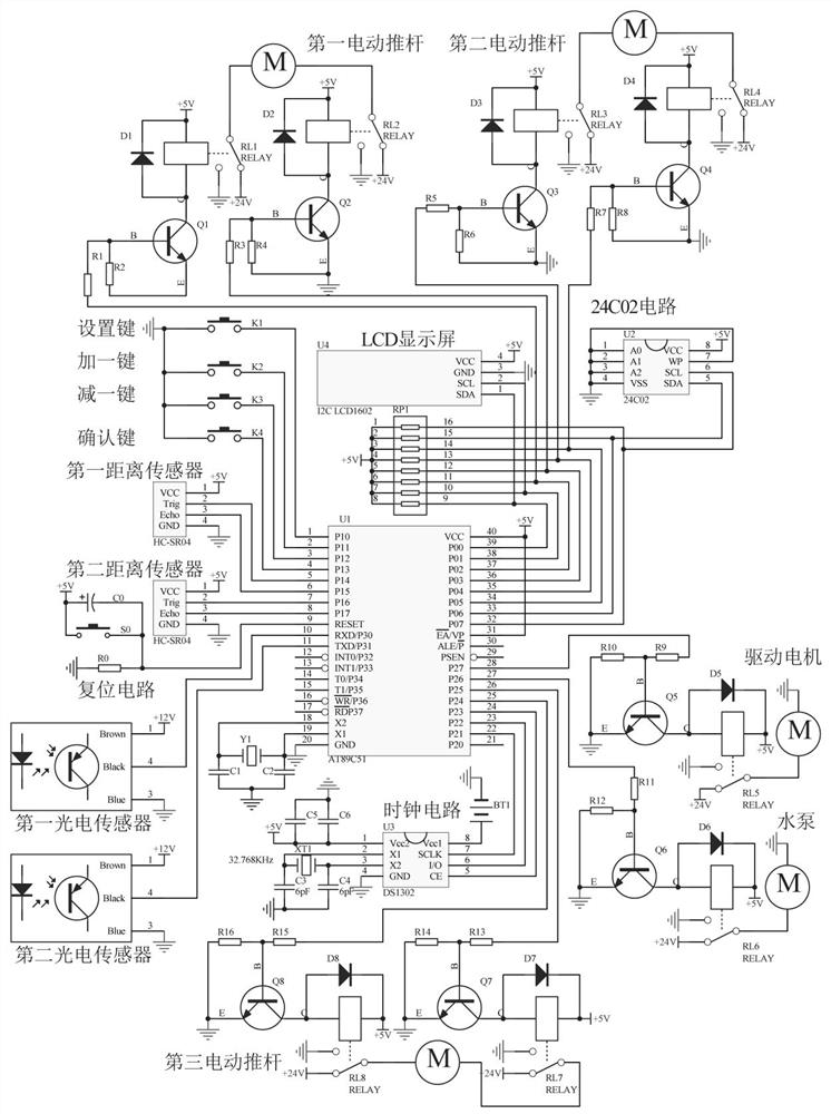
[0033] On the basis of embodiment one, refer to image 3 , also includes a thickness adjustment device 14, the thickness adjustment device 14 includes a mounting plate 141, a third electric push rod 142, a first pressure cylinder 143, a connecting rod 144, a second pressure cylinder 145 and a second distance sensor 146, the lower hopper The right side of the bottom of 10 is connected with a mounting plate 141, the mounting plate 141 is located on the right side of the discharge pipe 11, the third electric push rod 142 is installed on the mounting plate 141, and the mounting plate 141 is connected with the third electric push rod 142 by means of bolt connection , the bottom end of the third electric push rod 142 is equipped with a first pressure cylinder 143, the front side of the third electric push rod 142 is connected with a connecting rod 144, the connecting rod 144 is connected with the smear tube 13 in a rotational manner, and the support 9 is equipped with a second pressu...


PUM


Abstract

The invention relates to a cement mortar applicator, in particular to an automatic ceramic tile cement mortar applicator for building construction. The technical problem of the present invention is how to provide an automatic tile cement mortar applicator for building construction with high working efficiency and uniform application. An automatic ceramic tile cement mortar applicator for building construction, comprising a mounting frame, a retaining rod, a cross bar, etc.; a retaining rod is fixedly connected to the left side of the top of the mounting frame; The invention can pull the tiles to move to the right through the pulling device, so that the cement mortar flows on the tiles, and the cement mortar is applied, so that the cement mortar can be automatically applied, and the work efficiency is high. At the same time, the application pipe can move the cement mortar, so that the cement mortar can be uniform Applied on the tiles; the thickness of the cement mortar can be adjusted through the thickness adjustment device, so that it can be applied to different situations.

Description

technical field [0001] The invention relates to a cement mortar applicator, in particular to an automatic ceramic tile cement mortar applicator for building construction. Background technique [0002] Ceramic tiles are made of refractory metal oxides and semi-metal oxides as raw materials. After a series of processing, ceramic products are formed. Ceramic tiles are generally used in the construction industry to beautify buildings. Apply cement mortar. [0003] Usually construction workers apply cement mortar on the tiles with a trowel at present. When the tiles are large, construction workers need a long time to finish the application. The work efficiency is low and the application is not even enough. [0004] We design a device with high working efficiency and uniform coating to solve the above technical problems. Contents of the invention [0005] In order to overcome the shortcomings of construction workers applying cement mortar on tiles with a trowel, the work effic...

Claims


Application Information

Patent Timeline
Patent Type & Authority Patents(China)
IPC IPC(8): E04F21/02
CPCE04F21/023
Inventor 李乃元黄舒婷
Owner 李乃元
Learn More