Circumferential impact assembly
A component and impact hammer technology, applied in percussion drilling, drilling equipment and methods, construction, etc., can solve the problem that core components are easily damaged by erosion and continuous circumferential impact effects, etc., and achieve simple structure, easy processing, good stability effect
- Summary
- Abstract
- Description
- Claims
- Application Information
AI Technical Summary
Problems solved by technology
Method used
Image
Examples
Embodiment Construction
[0024] The present invention is not limited by the following examples, and specific implementation methods can be determined according to the technical solutions of the present invention and actual conditions.
[0025] In the present invention, for the convenience of description, the description of the relative positional relationship of each component is based on the description attached to the description. figure 1 For example, the positional relationship of front, rear, top, bottom, left, right, etc. is determined according to the layout direction of the drawings in the description.
[0026] Below in conjunction with embodiment and accompanying drawing, the present invention will be further described:
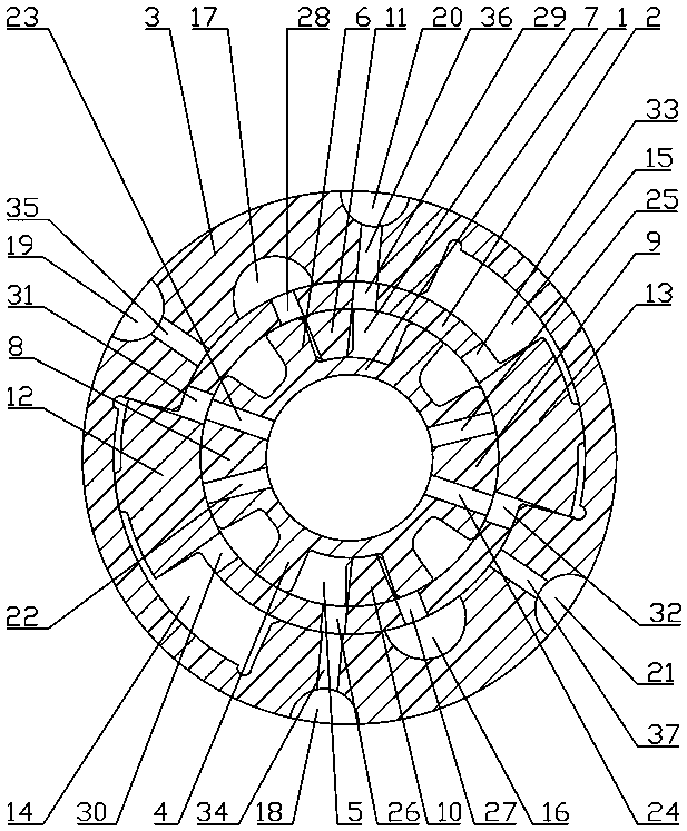
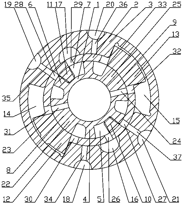
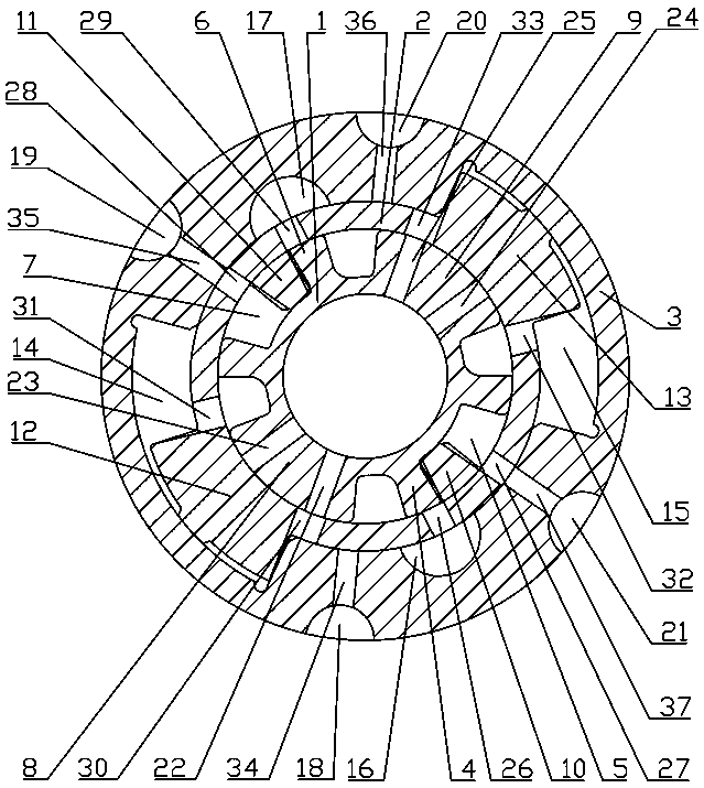
[0027] as attached figure 1 , 2, 3, 4, 5, 6, and 7, the circumferential impact assembly includes a flow plate 1, an arc-shaped boss, an impact hammer 2, a front vertical boss 10, a rear vertical boss 11, and a left hammer body 12 , the right hammer body 13, the anvil 3 an...
PUM
 Abstract
Description
Claims
Application Information
 - R&D
- Intellectual Property
- Life Sciences
- Materials
- Tech Scout
- Unparalleled Data Quality
- Higher Quality Content
- 60% Fewer Hallucinations
Browse by: Latest US Patents, China's latest patents, Technical Efficacy Thesaurus, Application Domain, Technology Topic, Popular Technical Reports.
© 2025 PatSnap. All rights reserved.Legal|Privacy policy|Modern Slavery Act Transparency Statement|Sitemap|About US| Contact US: help@patsnap.com


