Circumferential impact components

A component and impact hammer technology, applied in the direction of percussion drilling, rotary drilling, drilling equipment and methods, etc., can solve the problem that the core components are easily damaged by erosion and continuous circumferential impact effects, etc., and achieve simple structure, The effect of low operation and maintenance cost and easy processing

Active Publication Date: 2022-02-08
CNPC XIBU DRILLING ENG +1
View PDF6 Cites 0 Cited by
  • Summary
  • Abstract
  • Description
  • Claims
  • Application Information

AI Technical Summary

Problems solved by technology

[0004] The present invention provides a circumferential impact assembly, which overcomes the deficiencies of the prior art and can effectively solve the problems of the existing torsion impactors that the core components are easily damaged by erosion and the continuous circumferential impact effect is poor

Method used


Image

  • Circumferential impact components
  • Circumferential impact components
  • Circumferential impact components

Examples


Embodiment Construction

[0024] The present invention is not limited by the following examples, and specific implementation methods can be determined according to the technical solutions of the present invention and actual conditions.

[0025] In the present invention, for the convenience of description, the description of the relative positional relationship of each component is based on the description attached to the description. figure 1 For example, the positional relationship of front, rear, top, bottom, left, right, etc. is determined according to the layout direction of the drawings in the description.

[0026] Below in conjunction with embodiment and accompanying drawing, the present invention will be further described:

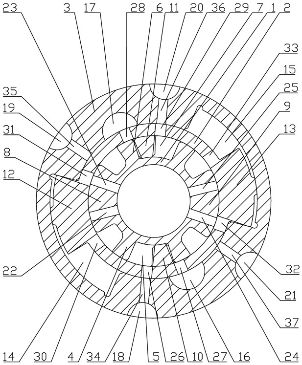
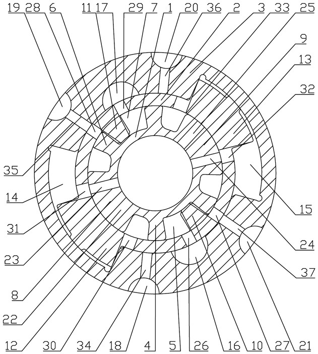
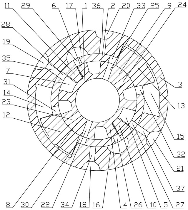
[0027] as attached figure 1 , 2, 3, 4, 5, 6, and 7, the circumferential impact assembly includes a flow plate 1, an arc-shaped boss, an impact hammer 2, a front vertical boss 10, a rear vertical boss 11, and a left hammer body 12 , the right hammer body 13, the anvil 3 an...


PUM


Abstract

The invention relates to the technical field of drilling equipment, and is a circumferential impact assembly, including a flow plate, an arc-shaped boss, an impact hammer, a front vertical boss, a rear vertical boss, a left hammer body, a right hammer body, and an anvil. And flow limiting parts, the middle part of the distribution plate is provided with a mandrel installation cavity that runs through up and down, and there are four arc-shaped bosses evenly distributed along the circumferential direction on the outside of the distribution plate. The middle part of the front boss is provided with a front arc-shaped gap with an upward opening. The invention is reasonable and compact in structure and easy to use. By setting the first slanted hole, the second slanted hole, the third slanted hole and the fourth slanted hole and putting them into flow limiting parts, the inner chamber of the anvil corresponding to the lower position of the flow plate A negative pressure area is formed to generate a strong negative pressure suction effect, which prevents irregular vortex flow between the distribution plate, impact hammer and anvil due to the reverse flow of drilling fluid, thereby reducing the impact of drilling fluid on the distribution plate, impact hammer and anvil. Erosion, with the characteristics of high efficiency, continuous reliability and long life.

Description

technical field [0001] The invention relates to the technical field of drilling equipment, and relates to a circumferential impact assembly. Background technique [0002] In the process of oilfield exploration and development, increasing the ROP is an eternal goal pursued by the oilfield development industry. At present, many different types of drilling speed-increasing tools have been developed at home and abroad and put into field test applications, and good results have been achieved. Existing drilling speed-up tools mainly achieve the speed-up effect by applying impact to the drill bit. According to the form of impact, they can be divided into axial impact speed-up devices and circumferential impact speed-up tools. The circumferential impact speed-up tool improves the working state of the PDC bit by applying periodic high-frequency circumferential impact force to the bit, improves the rock-breaking efficiency of the PDC bit, and then increases the ROP; at the same time,...

Claims


Application Information

Patent Timeline
Patent Type & Authority Patents(China)
IPC IPC(8): E21B3/00E21B12/00E21B11/00
CPCE21B3/00E21B12/00E21B11/00
Inventor 张昕乔东宇伊明王伟罡刘灵王维周张胜鹏李富强陈嘉陵张武涛
Owner CNPC XIBU DRILLING ENG
Why Eureka
Try Eureka