Drilling method for preventing water accumulation in goaf

A goaf and drilling technology, applied in drilling equipment and methods, drilling equipment, earth-moving drilling and mining, etc., can solve problems such as treating the symptoms but not the root cause, damaging the inner wall of the rock formation, and blocking the well due to the collapse of the rock formation, so as to improve productivity and yield. efficiency, reducing workover costs, and stabilizing well structure

Inactive Publication Date: 2020-04-17
山西蓝焰煤层气集团有限责任公司
View PDF5 Cites 4 Cited by
  • Summary
  • Abstract
  • Description
  • Claims
  • Application Information

AI Technical Summary

Problems solved by technology

The above-mentioned wellbore structure mainly exists that the aquifer in the open hole area will gushes a large amount of formation water into the goaf, causing the wall rock in the well to be leached, which will lead to two situations. (1) The long-term leaching and the gravity of the water make Some rock formations have collapsed and blocked wells. This situation can be solved by the workover team using air drilling, but the symptoms are not cured, and the inner wall of the rock formation will be damaged, resulting in a vicious cycle of more and more frequent workover cycles; (2) The aquifer is filled with the goaf shaft for a long time, and the water seal phenomenon occurs to seal the coalbed methane migration channel. In this case, a large-lift submersible pump is generally used to drain the water. This method cannot eradicate the water seal phenomenon, and the wellbore is easy to enter the air. Potential risk of gas combustion explosion
The adaptability analysis of the wellbore structure shows that it is difficult to meet the gas drainage requirements of the surface mined-out wells with the second open-hole completion method.

Method used


Image

  • Drilling method for preventing water accumulation in goaf

Examples


Embodiment Construction

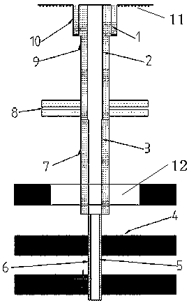
[0019] In order to have a clearer understanding of the technical features, purposes and effects of the present invention, the specific implementation manners of the present invention will now be described in detail with reference to the accompanying drawings.

[0020] A drilling method for preventing water accumulation in a goaf, the specific steps are as follows:

[0021] (1) Before designing the wellbore structure of the ground goaf, draw the aquifer joint well profile according to the surrounding hydrogeological conditions, and estimate the aquifer position of the local surface goaf well according to the aquifer joint well profile;

[0022] (2) drilling construction;

[0023] A 425mm drill bit is drilled to 10m below the bedrock weathering zone to form a drill hole, and a 377mm surface casing is lowered for cementing, and the cement is returned to the ground;

[0024] The second drilling 311mm drill bit is drilled to 10m below the lowest layer of aquifer in the upper part ...


PUM


Abstract

The invention belongs to the technical field of coalbed methane, and particularly relates to a drilling method for preventing water accumulation in a goaf. The drilling method for preventing water accumulation in the goaf aims to solve the problem mainly existing in a current well bore structure that a large amount of formation water gushing out of aquifers in an open hole area enters the goaf, and thus wall rock in a well is leached. The drilling method comprises the following specific steps that (1) joint well profiles of the aquifers are drawn through the surrounding hydrogeological condition, and positions of the aquifers of a ground mined-off well are estimated; and (2) drilling construction is conducted, specifically, a first-spud drill bit of 425 mm drills to the depth of 10 m belowa weathering belt of bedrock, a surface casing of 377 mm is driven in for well cementation, and cement is returned to the ground; a second-spud drill bit of 311 mm drills to the depth of 10 m below the last aquifer on the upper part of the goaf, then an intermediate casing of 273 mm is driven in for well cementation, and cement is returned to the ground; and a third-spud drill bit of 241.5 mm drills to a bottom plate of the goaf of a coal seam by 10 m for finishing a hole, or to a position of complete slurry (wind) leakage for finishing a hole, and barefoot well completion is conducted. The drilling method for preventing water accumulation in the goaf greatly reduces accidents of well collapse, well plugging and well flooding, thereby reducing the workover cost caused by the accidents.

Description

technical field [0001] The invention belongs to the technical field of coal bed gas, and in particular relates to a drilling method for preventing water accumulation in goafs. Background technique [0002] The original surface mining empty well adopts the structure of the second-opening open hole, that is, the first-opening 311mm drill bit, after drilling to the bedrock weathered zone, the 244.5mm surface casing is lowered for cementing, and the cement is returned to the ground to establish the wellhead; the second-opening 215.9mm drill bit is drilled Open hole completion in the goaf or to the place where the slurry (wind) leakage is serious. The above-mentioned wellbore structure mainly has a large amount of formation water gushing out from the aquifer in the open hole area into the goaf, causing the wall rock in the well to be leached, which will lead to two situations. (1) Long-term leaching and the gravity of water make Some rock formations have collapsed and blocked we...

Claims


Application Information

Patent Timeline
Patent Type & Authority Applications(China)
IPC IPC(8): E21B7/20E21B33/13
CPCE21B7/20E21B33/13
Inventor 王欣斌王争王宇鹏于振锋张思捷
Owner 山西蓝焰煤层气集团有限责任公司
Why Eureka
Try Eureka