

Waste heat recycling system and method based on organic Rankine recycle and organic flash recycle
A technology of waste heat recovery system and Rankine cycle, which is applied in the direction of machines/engines, steam applications, mechanical equipment, etc., can solve the problems of effective energy loss, improve the recovery ability, increase the net electric power output, and reduce the effective energy loss Effect
- Summary
- Abstract
- Description
- Claims
- Application Information
AI Technical Summary
Problems solved by technology
Method used
Image

Examples
Embodiment Construction
[0024] The present invention will be described in further detail below in conjunction with the accompanying drawings.
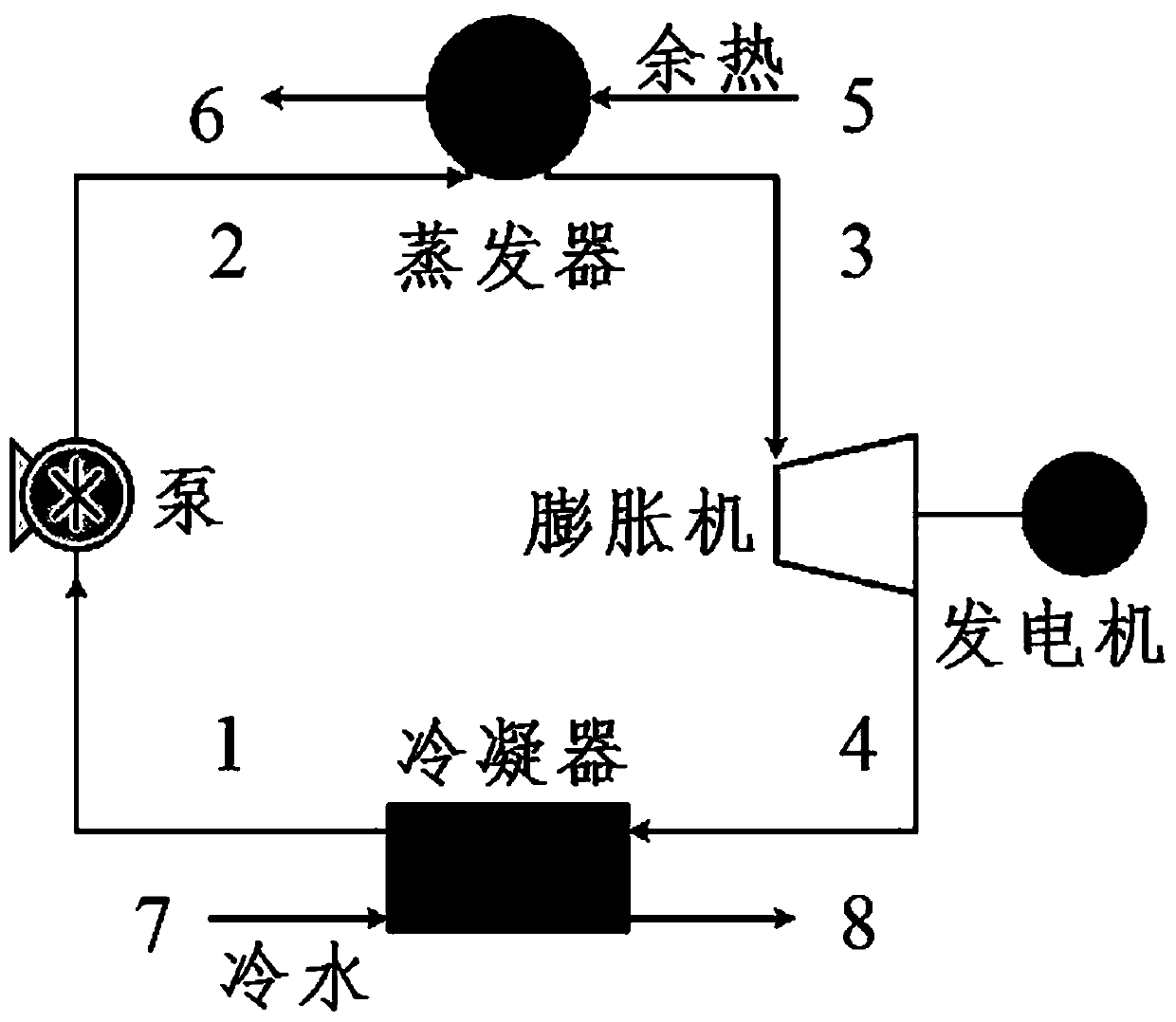
[0025] The traditional organic Rankine cycle-based waste heat recovery system consists of five main components, namely pump, evaporator, expander, condenser and generator. The system configuration is as follows: figure 1shown. In the traditional waste heat recovery system based on the organic Rankine cycle, the liquid organic working medium (state point 1) from the outlet of the condenser is pressurized by the pump and sent to the evaporator (state point 2); the liquid working medium in the evaporator Heated at constant pressure, from supercooled liquid state to saturated liquid state, gas-liquid two-phase state, and finally to saturated steam state (or superheated steam state), that is, state point 3; saturated steam (or superheated steam) is then sent to the expander De-expansion does work to output mechanical energy, the generator converts the mechanical ...
PUM
 Abstract
Description
Claims
Application Information