A water flow state conversion device inside a rigid pipeline

A technology for changing devices and pipelines, which is applied in the direction of rigid pipes, valve operating/release devices, valve devices, etc., and can solve problems such as inability to pass through multi-stage force stilling, ineffective buffering and energy reduction, and inconvenient control of liquid flow, etc., to achieve Significant cushioning energy dissipation effect, remarkable cushioning effect and remarkable wear resistance

Active Publication Date: 2021-09-03
LINAN PAIQI AIR PURIFYING TECH CO LTD
View PDF0 Cites 0 Cited by
  • Summary
  • Abstract
  • Description
  • Claims
  • Application Information

AI Technical Summary

Problems solved by technology

The existing water flow state transformation device cannot pass through multi-stage stilling, the effect of buffering and energy reduction is not obvious, and it is not convenient to control the liquid flow

Method used


Image

  • A water flow state conversion device inside a rigid pipeline
  • A water flow state conversion device inside a rigid pipeline
  • A water flow state conversion device inside a rigid pipeline

Examples


Embodiment 1

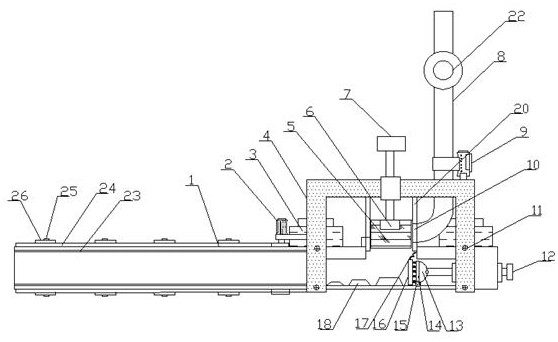
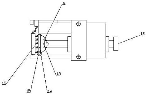
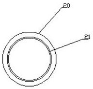
[0024] Such as Figure 1-4 As shown, a water flow state conversion device inside a rigid pipeline includes a water inlet pipe 1, an outlet pipe 8 and a mounting bracket 4, and the water inlet pipe 1 is equipped with a mounting bracket 4 through fastening screws 11, and the water inlet pipe 1 The top output port is welded with a connecting pipe 20, the connecting pipe 20 is provided with a piston 5, the top of the piston 5 is embedded with a bearing 6, and one end of the connecting pipe 20 is connected to the water outlet pipe 8 through the liquid outlet 10, and The outlet pipe 8 runs through the installation bracket 4, and the top end of the installation bracket 4 is equipped with a No. 2 flow velocity sensor 9 through the mounting seat, and a No. 1 flow velocity sensor 2 is installed on one end of the installation bracket 4 through the installation plate. The bottom is equipped with a stilling table 18 through set screws, and one end of the said stilling table 18 is connected...

Embodiment 2

[0038] Such as Figure 1-4As shown, a water flow state conversion device inside a rigid pipeline includes a water inlet pipe 1, an outlet pipe 8 and a mounting bracket 4, and the water inlet pipe 1 is equipped with a mounting bracket 4 through fastening screws 11, and the water inlet pipe 1 The top output port is welded with a connecting pipe 20, the connecting pipe 20 is provided with a piston 5, the top of the piston 5 is embedded with a bearing 6, and one end of the connecting pipe 20 is connected to the water outlet pipe 8 through the liquid outlet 10, and The outlet pipe 8 runs through the installation bracket 4, and the top end of the installation bracket 4 is equipped with a No. 2 flow velocity sensor 9 through the mounting seat, and a No. 1 flow velocity sensor 2 is installed on one end of the installation bracket 4 through the installation plate. The bottom is equipped with a stilling table 18 through set screws, and one end of the said stilling table 18 is connected ...


PUM


Abstract

The invention discloses a water flow state conversion device inside a rigid pipeline, comprising a water inlet pipe, a water outlet pipe and a mounting bracket, the water inlet pipe is mounted with a mounting bracket through fastening screws, and the top output port of the water inlet pipe is welded with a connection The connecting pipe is provided with a piston, the top of the piston is embedded with a bearing, one end of the connecting pipe is connected to the water outlet pipe through the liquid outlet, and the water outlet pipe runs through the installation bracket, and the top end of the installation bracket is installed The No. 2 flow velocity sensor is installed on the seat, and the No. 1 flow velocity sensor is installed on one end of the mounting bracket through the mounting plate. A stilling platform is installed on the inner bottom of the water inlet pipe through a positioning screw, and one end of the stilling platform is connected with a damping shaft. A fixed cover, one end of the fixed cover is installed with a connecting plate through bolts. The water flow state conversion device inside the novel rigid pipeline has various functions, is simple to operate, is convenient to produce, meets various demands in use, and is suitable for wide popularization and use.

Description

technical field [0001] The invention relates to the technical field of liquid transportation, in particular to a water flow state conversion device inside a rigid pipeline. Background technique [0002] The water flow in the pressure water pipe is flowing rapidly. It is necessary to decelerate the water flow through the stilling equipment to reduce the potential energy and protect the pipe body. After the reduction, the flow state of the water flow will change, reduce the heat generated by mechanical energy, and avoid excessive water temperature. The existing water flow state conversion device cannot pass through multi-stage stilling, the effect of buffering and reducing energy is not obvious, and it is not convenient to control the flow of liquid. For this reason, we propose a water flow state transformation device inside a rigid pipe. Contents of the invention [0003] The main purpose of the present invention is to provide a water flow state conversion device inside a ...

Claims


Application Information

Patent Timeline
Patent Type & Authority Patents(China)
IPC IPC(8): F16L55/02F16L57/06F16L58/04F16L9/14F17D5/00F16K1/32F16K31/60
CPCF16K1/32F16K31/60F16L9/14F16L55/02F16L57/06F16L58/04F17D5/00
Inventor 马亚囡
Owner LINAN PAIQI AIR PURIFYING TECH CO LTD
Why Eureka
Try Eureka