Beam bridge damage detection method based on elastic constraint supporting beam corner influence line

An elastic constraint and damage detection technology, which is applied in the field of bridge damage diagnosis, can solve the problems of bridge damage identification accuracy, bridge failure, poor work durability, etc., achieve effective quantification of beam structure damage, solve the problem of difficult installation of sensors, and sensitivity of damage diagnosis good sex effect

Active Publication Date: 2020-04-17
ANHUI UNIVERSITY OF ARCHITECTURE
View PDF6 Cites 12 Cited by
  • Summary
  • Abstract
  • Description
  • Claims
  • Application Information

AI Technical Summary

Problems solved by technology

However, these methods all face the problems of difficult installation of sensors in deflection and strain measurement, poor working durability, etc., and do not consider the vertical elastic support boundary of the beam end caused by the elastic deformation or settlement of the pier foundation, and do not consider the initial structure of the bridge. Model Uncertainty Effects
At present, some scholars have established a main beam model considering the uncertainty of bending stiffness, and carried out damage identification based on the difference of mid-span displacement influence lines, and used wooden bridge model tests to verify the proposed method; some scholars believe that corner influence lines are convenient for installation and testing, and consider Due to the uncertain factors of the initial model, a damage detection method for simply supported beam structures based on the angle influence line was proposed, but the above research did not fully consider the influence of the non-ideal support boundary of the bridge model, which affected the accuracy of bridge damage identification

Method used


Image

  • Beam bridge damage detection method based on elastic constraint supporting beam corner influence line
  • Beam bridge damage detection method based on elastic constraint supporting beam corner influence line
  • Beam bridge damage detection method based on elastic constraint supporting beam corner influence line

Examples


Embodiment Construction

[0032] The technical solutions in the embodiments of the present invention will be clearly and completely described below in conjunction with the accompanying drawings in the embodiments of the present invention. Obviously, the described embodiments are only part of the embodiments of the present invention, not all of them. Based on the embodiments of the present invention, all other embodiments obtained by persons of ordinary skill in the art without making creative efforts belong to the protection scope of the present invention.

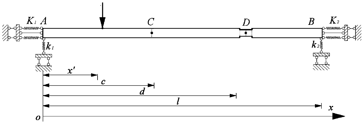
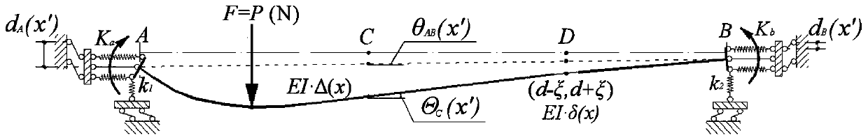
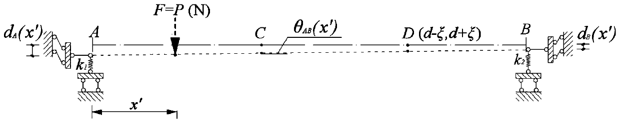
[0033] A beam bridge damage detection method based on elastically constrained support beam angle influence lines, the method includes the following steps:

[0034] Step 1: Establish an elastically constrained beam model in line with the actual engineering situation: set a pair of springs parallel to the longitudinal axis of the beam on the beam end section and lower edge to achieve elastic rotation constraint;

[0035] where the stiffness is K 1 T...


PUM


Abstract

The invention discloses a beam bridge damage detection method based on an elastic constraint supporting beam corner influence line. The method comprises the steps of model establishment, corner influence line analysis and damage diagnosis implementation. According to the method, accurate positioning can be achieved based on the elastic constraint supporting beam corner influence line, beam type structure damage is effectively quantified, the relative error is small, and the index noise immunity is good; based on the corner influence line index, adjacent span damage can be diagnosed by arranging corner measuring points on a specific span of the continuous beam bridge, and when the beam end rotation constraint is weak, the damage diagnosis sensitivity is better; according to the method, theproblem that sensors are not easy to install in application based on deflection and strain influence line damage diagnosis can be effectively solved, the proposed influence line loading implementationscheme is reasonable and feasible, quick diagnosis of beam bridge damage can be achieved, and reference is provided for implementation of corner influence line analysis and quick damage diagnosis ofan existing beam bridge.

Description

technical field [0001] The invention belongs to the field of bridge damage diagnosis, in particular to a beam bridge damage detection method based on the influence line of the rotation angle of an elastically constrained support beam. Background technique [0002] Using the influence line method to monitor the service state of the bridge can reflect the structural stiffness and load information of the bridge to the greatest extent under the premise of installing a small number of sensors. The common test object is the deflection or stress influence line. Considering the rotational elastic constraints, the railway bridge and curved bridge structure models are established, and the bridge damage diagnosis is carried out by using the displacement influence line and its curvature, which provides a reference for diagnosing the damage of beam structures with non-ideal boundary conditions; The research on damage identification is carried out, and the feasibility of identifying struc...

Claims


Application Information

Patent Timeline
Patent Type & Authority Applications(China)
IPC IPC(8): G01M99/00G01M5/00G06F30/13
CPCG01M5/0008G01M5/0041G01M99/007
Inventor 周宇万杨旭吴侃黄浩刘金澳李宁
Owner ANHUI UNIVERSITY OF ARCHITECTURE
Why Eureka
Try Eureka