Cable water blocking method

A cable and water blocking technology, which is used in equipment for connecting/terminating cables, repairing equipment for insulated/armored cables, etc. It can solve the problems of cable failure, low reliability and safety, and achieve improved reliability and increased service life. , the effect of increasing the longitudinal water resistance

Inactive Publication Date: 2020-04-17
THE 715TH RES INST OF CHINA SHIPBUILDING IND CORP
View PDF9 Cites 0 Cited by
  • Summary
  • Abstract
  • Description
  • Claims
  • Application Information

AI Technical Summary

Problems solved by technology

The horizontal watertight cable can only keep the cable radially watertight. Once the radial watertightness is destroyed, the water will spread axially against the cable under the action of water pressure, making the whole cable invalid, so it can only be used for those with low reliability and safety. Longitudinal watertight cables must not only maintain horizontal watertightness, but also limit the speed of water diffusion in the axial direction after the radial watertightness is broken. All cables passing through the pressure-resistant shell are required to be longitudinal watertight cables.

Method used


Image

  • Cable water blocking method
  • Cable water blocking method

Examples


Embodiment 1

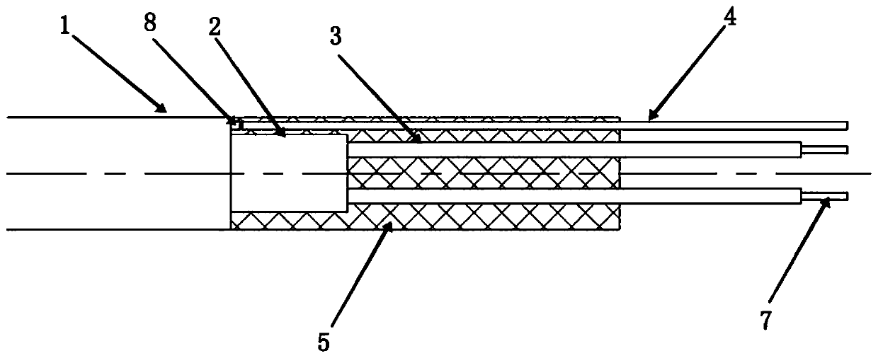
[0019] Embodiment 1: A kind of cable water blocking method, such as figure 1 Applied to the cable end, the method includes the following steps:

[0020] Step 1: Strip off the outer sheath 1, inner sheath 2, core wire insulation layer 3 of a certain length of cable in turn at the end of the cable and expose the core wire 7, so that the outer sheath 1, inner sheath 2 and core wire The stripped length of the insulating layer 3 along the length direction decreases successively;

[0021] Step 2: When water-blocking treatment is performed on the end of the cable, the shielded wire 8 is cut off at the end face near the outer sheath 1, and the broken point is connected to the bare copper wire 4 with solder.

[0022] Step 3: Using rubber 5 or polyurethane 6 to rebond the outer sheath 1, the inner sheath 2 and the core wire insulation layer 3 together.

Embodiment 2

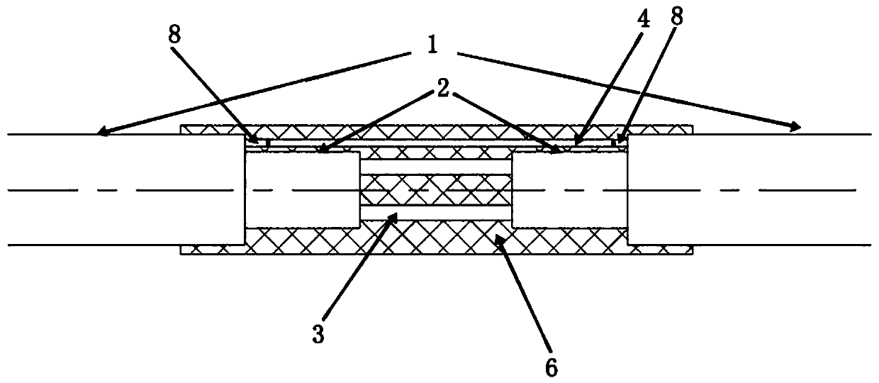
[0023] Embodiment 2: A kind of cable water blocking method, such as figure 2 Applied to the middle of the cable, the method includes the following steps:

[0024] Step 1: In the middle of the cable, peel off the outer sheath 1 and inner sheath 2 of a certain length of cable and expose the core wire insulation layer 3, so that the outer sheath 1, inner sheath 2 and core wire insulation layer 3 are along the length The stripped length in each direction decreases successively.

[0025] Step 2: When performing water-blocking treatment on the middle part of the cable, cut off the shielded wire 8 at the end faces on both sides of the outer sheath 1 respectively, and connect the two breakpoints with the bare copper wire 4 with solder.

[0026] Step 3: Use rubber 5 or polyurethane 6 to rebond the outer sheath 1, inner sheath 2 and core wire insulation layer 3 together, that is, use rubber vulcanization or polyurethane perfusion.

[0027] As another preferred technical solution: on ...


PUM


Abstract

The invention discloses a cable water blocking method. The method comprises the following steps: 1, sequentially stripping an outer sheath and an inner sheath of a certain length of a cable, exposinga core wire insulating layer, and enabling the outer sheath, the inner sheath and the core wire insulating layer to be arranged in a stepped manner in the length direction; 2, cutting off the shielding wire at a position close to the end surface of the outer sheath, and connecting a breakpoint with the bare copper wire by soldering tin; and 3, re-bonding the outer sheath, the inner sheath and thecore wire insulating layer together by adopting rubber or polyurethane. The beneficial effects of the method are that the longitudinal water-blocking capability of the cable is improved, and the diffusion of water in the axial direction of the cable is limited in a certain range; the cable processed by the method has the characteristics of prolonged service life and improved reliability, and the method is suitable for various cables which are used underwater for a long time.

Description

technical field [0001] The invention relates to the field of cables, and mainly relates to a cable water blocking method. Background technique [0002] The 21st century is the century of the ocean. Marine equipment and naval equipment have developed greatly. Underwater cables are an indispensable part of marine equipment and naval equipment. At present, the development speed of underwater cables cannot keep up with the pace of marine equipment and naval equipment, and the life and reliability do not meet the requirements for use. Therefore, it is imperative to improve the life and reliability of underwater cables. [0003] There are two types of underwater cables, namely horizontal watertight cables and longitudinal watertight cables. The horizontal watertight cable can only keep the cable radially watertight. Once the radial watertightness is destroyed, the water will spread axially against the cable under the action of water pressure, making the whole cable invalid, so i...

Claims


Application Information

Patent Timeline
IPC IPC(8): H02G1/16H02G1/14
CPCH02G1/14H02G1/16
Inventor 寇红军孔海防刘强李坚赵圣尉
Owner THE 715TH RES INST OF CHINA SHIPBUILDING IND CORP
Why Eureka
Try Eureka