Motor out-of-step compensation method and device

A compensation value and level technology, applied in the field of motor out-of-step compensation methods and devices, can solve problems such as lens out-of-focus and image blurring, and achieve the effect of improving lens out-of-focus and solving lens out-of-focus

Active Publication Date: 2020-04-17
苏州智感电子科技有限公司
View PDF6 Cites 2 Cited by
  • Summary
  • Abstract
  • Description
  • Claims
  • Application Information

AI Technical Summary

Problems solved by technology

[0005] The purpose of the present invention is to provide a motor out-of-step compensation method and device to solve the problems of out-of-focus lens and blurred picture image caused by motor out-of-step

Method used


Image

  • Motor out-of-step compensation method and device
  • Motor out-of-step compensation method and device
  • Motor out-of-step compensation method and device

Examples


Embodiment Construction

[0025] The present invention will be described in detail below in conjunction with the implementations shown in the drawings, but it should be noted that these implementations are not limitations of the present invention, and those of ordinary skill in the art based on the functions, methods, or structural changes made by these implementations Equivalent transformations or substitutions all fall within the protection scope of the present invention.

[0026] The technical solutions provided by various embodiments of the present invention will be described in detail below in conjunction with the accompanying drawings.

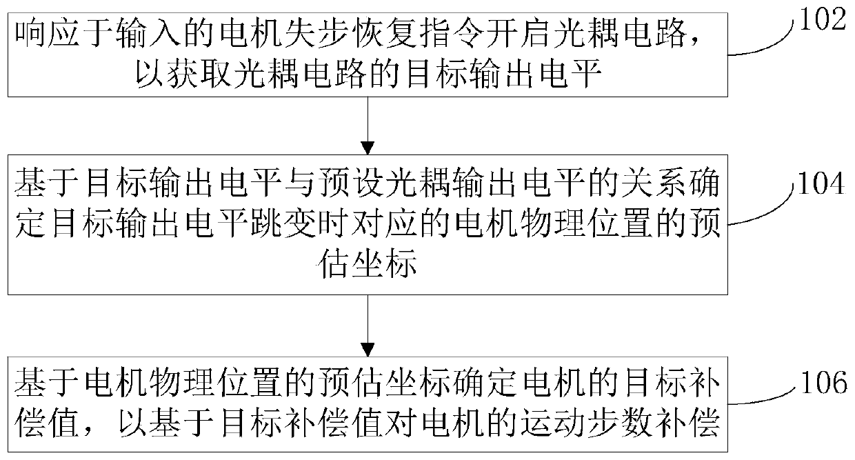
[0027] figure 1 It is a schematic flowchart of a motor out-of-step compensation method according to an embodiment of the present invention, which solves the problems of out-of-focus lens and blurred picture image caused by motor out-of-step. The method includes:

[0028] Step 102. Turn on the optocoupler circuit in response to the input motor out-of-step recove...


PUM


Abstract

The invention provides a motor out-of-step compensation method and device, and the method comprises the steps: starting an optical coupling circuit in response to an inputted motor out-of-step recovery instruction so as to obtain the target output level of the optical coupling circuit; determining estimated coordinates of a corresponding motor physical position when the target output level jumps based on the relationship between the target output level and a preset optocoupler output level; and determining the target compensation value of the motor based on the estimated coordinates of the motor physical position so as to compensate the motion step number of the motor based on the target compensation value. The problems of lens out-of-focus and blurred image imaging caused by out-of-step of the motor are solved.

Description

technical field [0001] The invention relates to the field of motor drive, in particular to a motor out-of-step compensation method and device. Background technique [0002] The motor is an open-loop control motor that converts electrical pulse signals into angular displacement or linear displacement. In the case of non-overload, the speed and stop position of the motor only depend on the frequency and number of pulse signals, and are not affected by load changes. Influence, when the stepper driver receives a pulse signal, it will drive the motor to rotate a fixed angle in the set direction, called "step angle", its rotation is run step by step at a fixed angle, which can be passed Control the number of pulses to control the angular displacement, so as to achieve the purpose of accurate positioning; at the same time, the speed and acceleration of the motor rotation can be controlled by controlling the pulse frequency, so as to achieve the purpose of speed regulation. [0003...

Claims


Application Information

Patent Timeline
Patent Type & Authority Applications(China)
IPC IPC(8): H02P8/38
CPCH02P8/38
Inventor 不公告发明人
Owner 苏州智感电子科技有限公司
Why Eureka
Try Eureka