Syringe body

A technology for syringes and drug injectors, which is applied in the direction of syringes, ampoule syringes, hypodermic injection devices, etc. It can solve problems such as easy tilting of the syringe body and storage problems of the syringe body, and achieve improved readability, reduced incidence, and good grip Effect

Active Publication Date: 2020-04-21
肖特制药瑞士股份公司
View PDF13 Cites 0 Cited by
  • Summary
  • Abstract
  • Description
  • Claims
  • Application Information

AI Technical Summary

Problems solved by technology

[0011] However, it has been found that such a configuration with e.g. longitudinal ribs causes storage problems of the syringe body: a syringe body cast according to the above principles tends to tilt if placed on a flat surface with its flange surface

Method used


Image

  • Syringe body
  • Syringe body
  • Syringe body

Examples


Embodiment Construction

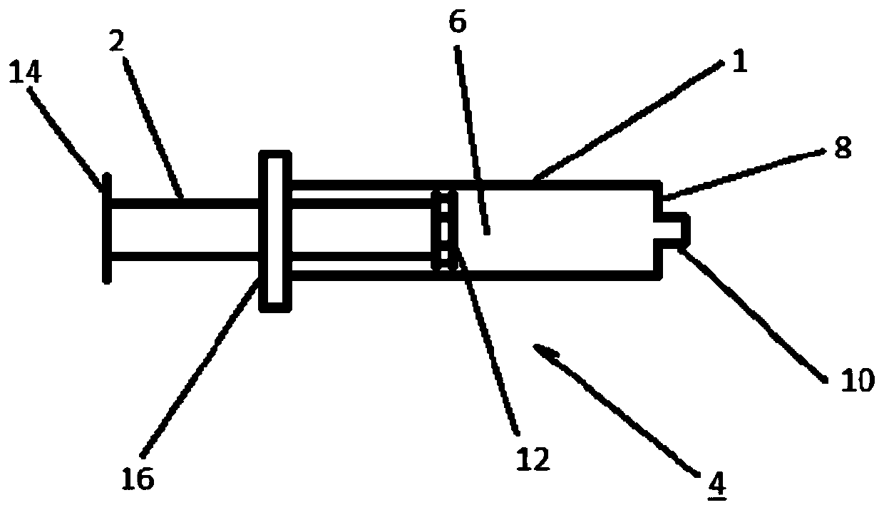
[0053] figure 1 A schematic view of a syringe body 1 with a piston 2 is shown, which together form a medicament syringe 4 . The syringe body 1 is made of transparent plastic, in this example a cycloolefin polymer or copolymer. It comprises a cavity 6 with cylindrical walls. The wall is substantially closed at the first end face 8 , but the liquid located in the cavity 6 can also be forced out there via the cone 10 . This is achieved by squeezing the piston 2 inwards so that the piston head 12 , which is round and in seamless contact with the wall of the cavity 6 , exerts pressure on the liquid.

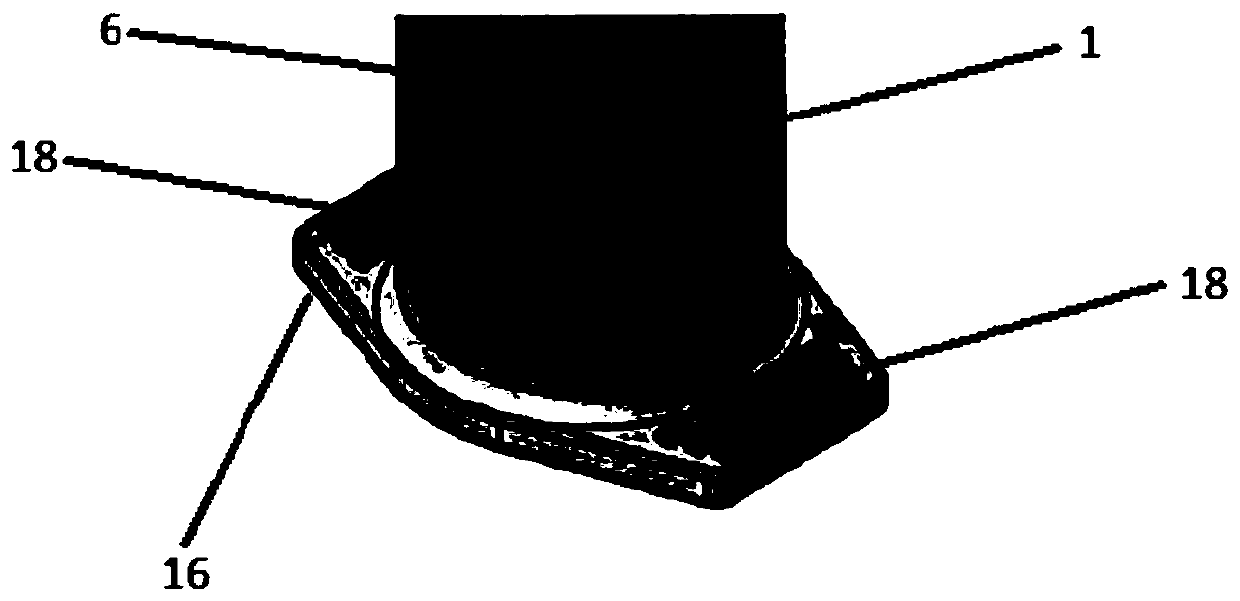
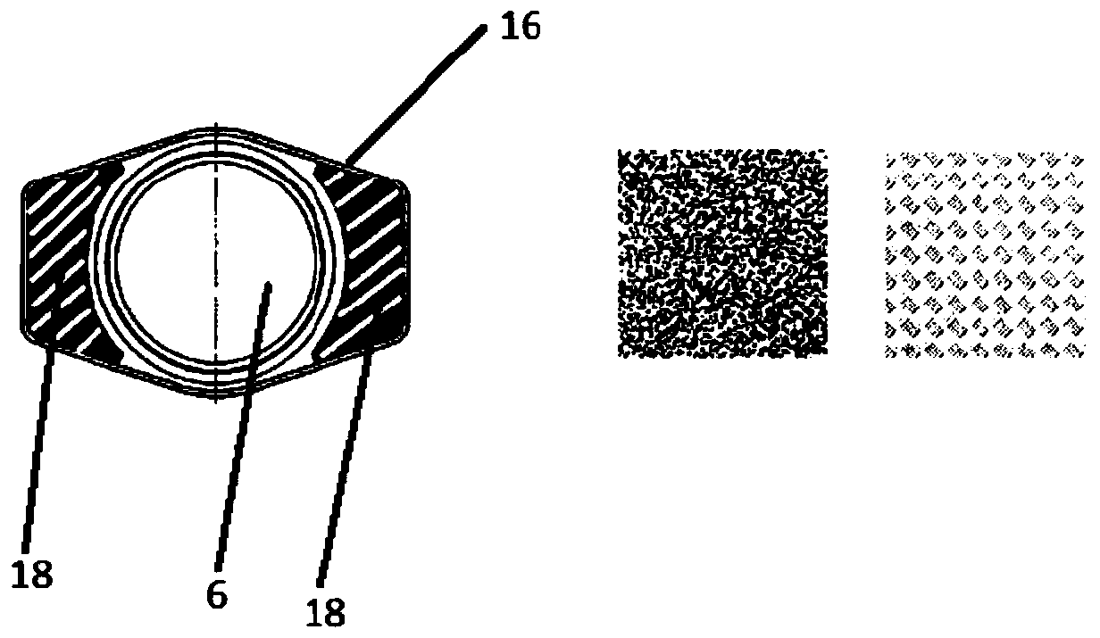
[0054] For inserting the piston 2 into the cavity 6, the cavity is open on the second end face of the cylinder. In order to press the piston 2 inwards, it has, on the side opposite the piston head 12 , a pressing surface 14 which is normally actuated by means of the user's thumb. To apply counter pressure, a collar is cast around the circular orifice of the cavity 6 flange 16 fo...


PUM


Abstract

The present invention relates to a syringe body for a drug or cosmetic syringe and a method for administering a drug or cosmetic, the syringe body comprising a cylindrical cavity having: a first end face with a cone; a second open end surface into which the piston is inserted; and a flange for the finger, which is arranged in the circumferential region of the open end face, the flange for the finger having, on the side facing the cone, a non-slip element for preventing slipping of the finger during injection.

Description

technical field [0001] The present invention relates to a syringe body for a drug or cosmetic syringe and a method for administering the drug or cosmetic product, said syringe body comprising a cylindrical cavity having: a first end surface with a taper; the second open end face for insertion into the piston; and a flange for the fingers, which is arranged in the circumferential region of the open end face, wherein the flange for the fingers has an anti-slip element on the side facing the cone for Prevent slipping of fingers during injection. Background technique [0002] A drug injector refers to a medical device for applying (injecting) liquid or fluid drugs or cosmetics (so-called injections, which are generally also simply referred to as fluids within the scope of the present disclosure). A syringe generally includes a syringe body having a cylindrical cavity and a plunger that moves therein. On the end face of the cylinder there is usually a cone, possibly also a thre...

Claims


Application Information

Patent Timeline
Patent Type & Authority Applications(China)
IPC IPC(8): A61M5/178A61M5/31A61F9/00
CPCA61M5/178A61M5/3137A61F9/0008A61M2005/3139A61M5/28A61M5/3135A61M5/007A61J7/0053A61M5/315
Inventor M·库祖克
Owner 肖特制药瑞士股份公司
Why Eureka
Try Eureka