Humidifying tank
A humidification tank and humidification technology, applied in the field of medical devices, can solve the problems of large impedance, lower airflow output efficiency of ventilation treatment equipment, complex structure, etc., and achieve the effects of reducing airflow impedance, improving airflow output efficiency, and reducing damage probability
- Summary
- Abstract
- Description
- Claims
- Application Information
AI Technical Summary
Problems solved by technology
Method used
Image

Examples
Embodiment 1
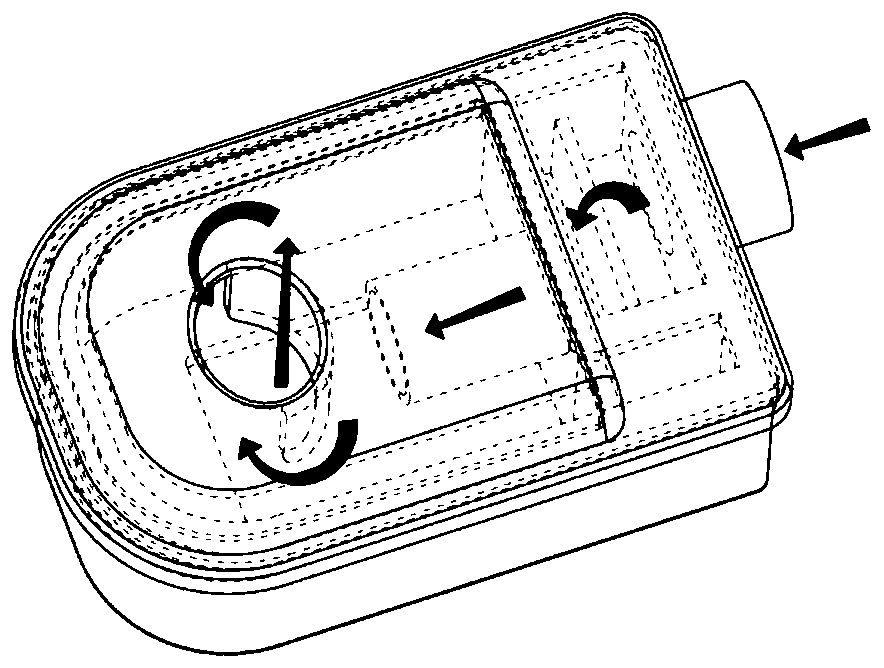
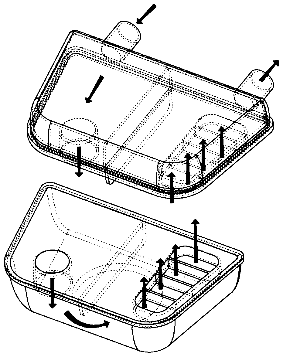
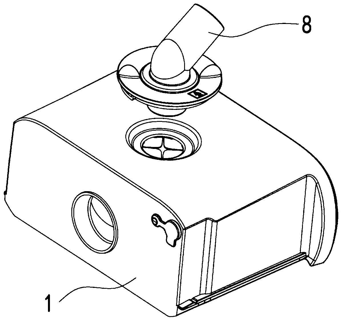
[0055] Figure 3-4 It is a structural schematic diagram of Embodiment 1 of the humidification tank of the present invention. A humidification tank includes a humidification tank main body 1, and the humidification tank main body 1 includes an accommodating cavity for containing humidification liquid The humidification tank main body 1 also includes an air outlet 3 arranged on the top wall of the accommodating cavity 1 and an air inlet pipe 2 arranged on a side wall of the accommodating chamber, the air inlet pipe 2 has an air inlet 21 and an air outlet 22, the lower part of the air inlet 21 is higher than the lower part of the air outlet 22 in the horizontal direction, so that the air inlet pipe 2 is in a downward trend in the humidification tank main body 1 as a whole, and the length of the air inlet pipe 2 is greater than or equal to the humidification Half of the length of the air inlet pipe 2 of the tank main body 1, that is, the air outlet end 22 of the air inlet pipe 2 i...
Embodiment 2
[0057] Figure 5 It is a structural schematic diagram of Embodiment 2 of the humidification tank of the present invention. A humidification tank includes a humidification tank main body 1, and the humidification tank main body 1 includes an accommodating cavity for containing humidification liquid The humidification tank main body 1 also includes an air outlet 3 arranged on the top wall of the accommodating cavity 1 and an air inlet pipe 2 arranged on a side wall of the accommodating chamber, the air inlet pipe 2 has an air inlet 21 and an air outlet 22, the lower part of the air inlet 21 is higher than the lower part of the air outlet 22 in the horizontal direction, so that the air inlet pipe 2 is in a downward trend in the humidification tank main body 1 as a whole, and the length of the air inlet pipe 2 is greater than or equal to the humidification Half of the length of the inlet pipe 2 of the tank body 1, that is, the outlet end 22 of the inlet pipe 2 is in the middle of ...
Embodiment 3
[0059] Image 6 It is a schematic diagram of the third embodiment of the humidification tank of the present invention. A humidification tank includes a humidification tank main body 1, and the humidification tank main body 1 includes an accommodating cavity for containing humidification liquid The humidification tank main body 1 also includes an air outlet 3 arranged on the top wall of the accommodating cavity 1 and an air inlet pipe 2 arranged on a side wall of the accommodating chamber, the air inlet pipe 2 has an air inlet 21 and an air outlet 22, the lower part of the air inlet 21 is higher than the lower part of the air outlet 22 in the horizontal direction, so that the air inlet pipe 2 is in a downward trend in the humidification tank main body 1 as a whole, and the length of the air inlet pipe 2 is greater than or equal to the humidification Half of the length of the tank main body 1 in the direction of the air inlet pipe 2, that is, the air outlet end 22 of the air inl...
PUM
 Abstract
Description
Claims
Application Information
 - R&D
- Intellectual Property
- Life Sciences
- Materials
- Tech Scout
- Unparalleled Data Quality
- Higher Quality Content
- 60% Fewer Hallucinations
Browse by: Latest US Patents, China's latest patents, Technical Efficacy Thesaurus, Application Domain, Technology Topic, Popular Technical Reports.
© 2025 PatSnap. All rights reserved.Legal|Privacy policy|Modern Slavery Act Transparency Statement|Sitemap|About US| Contact US: help@patsnap.com