A high-speed cam bending machine

A high-speed cam, bending machine technology, applied in storage devices, metal processing equipment, feeding devices, etc., can solve problems such as general working efficiency of bending machines

Inactive Publication Date: 2021-06-22
山东郓城骏通专用车有限公司
View PDF0 Cites 0 Cited by
  • Summary
  • Abstract
  • Description
  • Claims
  • Application Information

AI Technical Summary

Problems solved by technology

[0003] The current working efficiency of the bending machine is average, and those skilled in the art hope that the working efficiency of the bending machine can be further improved

Method used


Image

  • A high-speed cam bending machine
  • A high-speed cam bending machine
  • A high-speed cam bending machine

Examples


Embodiment 1

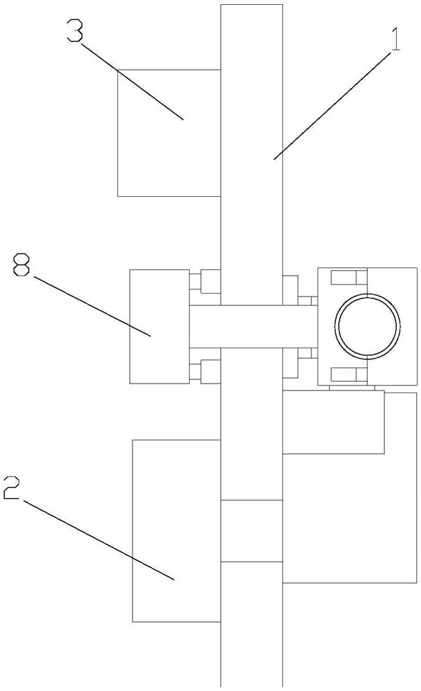
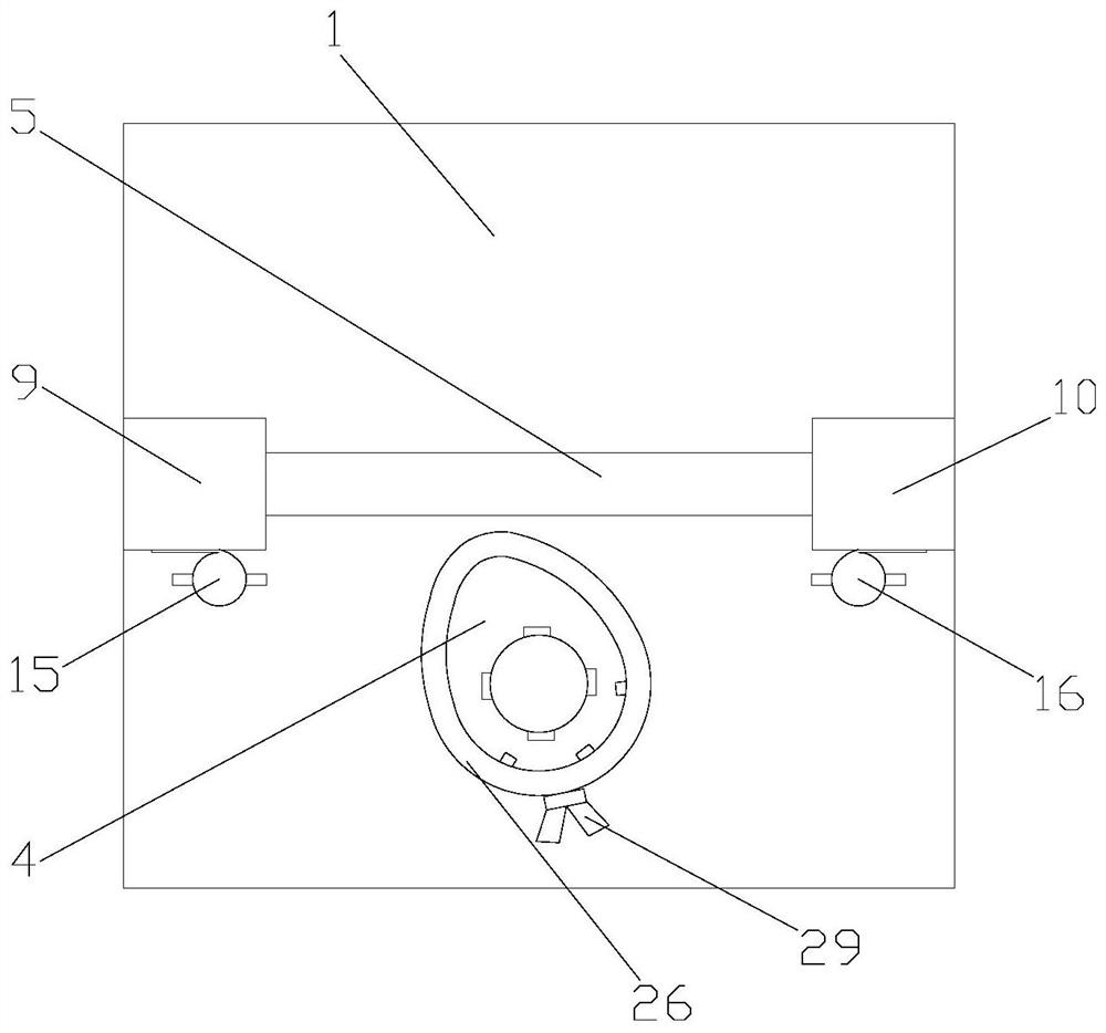
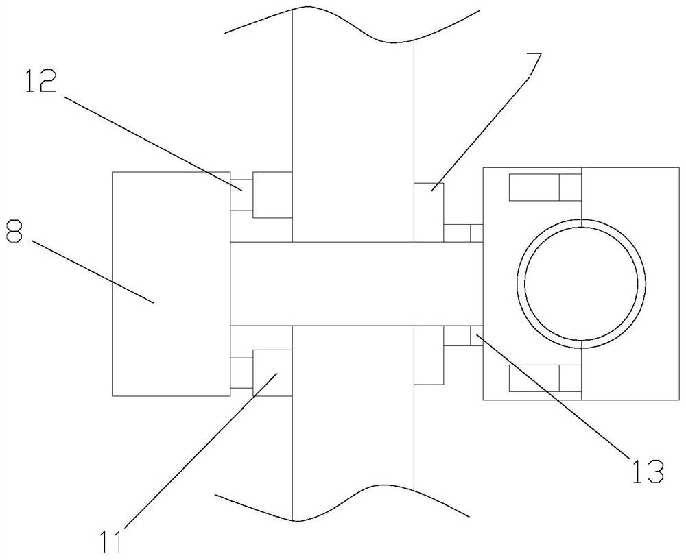
[0029] Such as Figure 1-5As shown, a high-speed cam bending machine includes a carrier plate 1, a geared motor 2 and a control device 3, and the carrier plate 1 is provided with a first perforation (not shown) and a first guide groove (not shown) , the output shaft of the geared motor 2 passes through the first perforation and a bending cam 4 is set, the output shaft of the geared motor 2 is detachably connected to the bending cam 4, and the geared motor 2 is fixed to the back of the carrier plate 1 connection, the carrier board 1 is provided with a first guide rail 5, the first guide rail 5 is provided with a second guide groove 6 corresponding to the first guide groove, and the first guide rail 5 is provided with a first slide 7 and a second slider (not shown), the first slider 7 is provided with a second through hole (not shown), the back of the carrier board 1 is provided with an encoder 8, the encoder 8 The input shaft passes through the first guide groove, the second g...

Embodiment 2

[0032] Such as Figure 1-7 As shown, a high-speed cam bending machine includes a carrier plate 1, a geared motor 2 and a control device 3, and the carrier plate 1 is provided with a first perforation (not shown) and a first guide groove (not shown) , the output shaft of the geared motor 2 passes through the first perforation and a bending cam 4 is set, the output shaft of the geared motor 2 is detachably connected to the bending cam 4, and the geared motor 2 is fixed to the back of the carrier plate 1 connection, the carrier board 1 is provided with a first guide rail 5, the first guide rail 5 is provided with a second guide groove 6 corresponding to the first guide groove, and the first guide rail 5 is provided with a first slide 7 and a second slider (not shown), the first slider 7 is provided with a second through hole (not shown), the back of the carrier board 1 is provided with an encoder 8, the encoder 8 The input shaft passes through the first guide groove, the second ...


PUM


Abstract

The invention discloses a high-speed cam bending machine, which includes a carrier plate, a geared motor and a control device. The carrier plate is provided with a first through hole and a first guide groove. The output shaft of the geared motor passes through the first through hole and The bending cam is set, the output shaft of the deceleration motor is detachably connected to the bending cam, the deceleration motor is fixedly connected to the back of the carrier plate, the carrier plate is provided with a first guide rail, and the first guide rail is provided with There is a second guide groove corresponding to the first guide groove, a first slider and a second slider are arranged on the first guide rail, a second through hole is arranged on the first slider, and the back of the carrier board is An encoder is provided, the first slider and the second slider are respectively provided with a first clamp and a second clamp, the input shaft of the encoder is fixedly connected with the first clamp, and the encoder slides with the carrier plate connection; the high-speed cam bending machine has high working efficiency.

Description

technical field [0001] The invention relates to a high-speed cam bending machine. Background technique [0002] A bending machine is a machine capable of bending objects. Its structure mainly includes a bracket, a workbench and a clamping plate. The workbench is placed on the bracket. The workbench is composed of a base and a pressure plate. The base is composed of a seat shell, a coil and a cover plate, the coil is placed in the depression of the seat shell, and the top of the depression is covered with a cover plate. When in use, the wire is energized to the coil, and after energization, an attractive force is generated on the pressure plate, so as to realize the clamping of objects between the pressure plate and the base. Due to the use of electromagnetic force clamping, the pressure plate can be made into a variety of workpiece requirements, and the workpiece with side walls can be processed, and the operation is also very simple. [0003] The working efficiency of the...

Claims


Application Information

Patent Timeline
Patent Type & Authority Patents(China)
IPC IPC(8): B21D11/22B21D11/00B21D43/00
CPCB21D11/00B21D11/22B21D43/003
Inventor 不公告发明人
Owner 山东郓城骏通专用车有限公司
Why Eureka
Try Eureka