
Welding positioning device for connecting seat

A welding positioning and connecting seat technology, which is applied to auxiliary devices, welding equipment, auxiliary welding equipment, etc., can solve the problems of difficult to guarantee accuracy and low welding efficiency, and achieve the effect of good positioning effect, easy welding, and reduction of types.

Pending Publication Date: 2020-04-21
HENAN BENMA
View PDF0 Cites 0 Cited by
  • Summary
  • Abstract
  • Description
  • Claims
  • Application Information

AI Technical Summary

Problems solved by technology

[0004] The purpose of the present invention is to provide a welding positioning device for the connecting seat, so as to solve the problems of low welding efficiency and difficulty in ensuring the accuracy of the positioning of the hinged ear plate by the traditional measurement method

Method used


Image

  • Welding positioning device for connecting seat
  • Welding positioning device for connecting seat
  • Welding positioning device for connecting seat

Examples


Embodiment Construction

[0021] The specific embodiments of the present invention will be further described below in conjunction with the accompanying drawings, but not limited thereto.

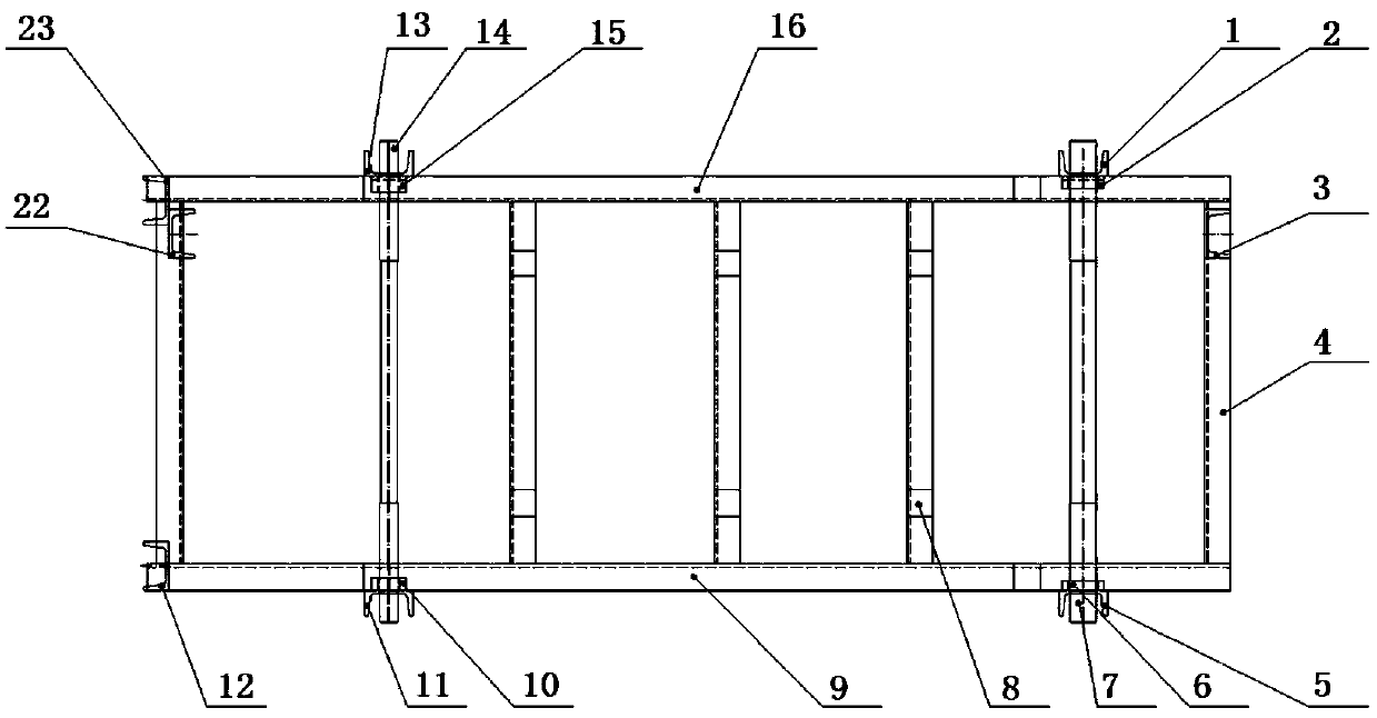
[0022] The specific embodiment of the welding positioning device of the connecting seat provided by the present invention, such as image 3 with Figure 4 As shown, the welding positioning device of the connecting seat includes a base positioning seat for positioning the base of the connecting seat, and the base positioning seat includes a left longitudinal beam 9 arranged in parallel, a right longitudinal beam 16 and a parallel welding on the left side The cross brace 4 between the longitudinal beam 9 and the right side beam 16. The left longitudinal beam 9 and the right longitudinal beam 16 are respectively erected with positioning pin inserting seats. The first side support 5 , the second left support 11 , the first right support 1 and the second right support 13 . Wherein, the left first support 5 and the righ...


PUM


Abstract

The invention relates to a welding positioning device for a connecting seat. The welding positioning device for the connecting seat comprises a base positioning seat used for positioning a base of theconnecting seat, positioning pieces used for positioning two longitudinal beams of the base in the direction perpendicular to the longitudinal beams are vertically arranged on the base positioning seat, and the positioning faces, used for positioning the two longitudinal beams of the base in the direction perpendicular to the longitudinal beams, of the positioning pieces are in the same orientation. By means of the technical scheme, the problems that when hinging lug plates of the connecting seat are positioned in a traditional measuring mode, the welding efficiency is low, and the welding precision is not easy to ensure are solved.

Description

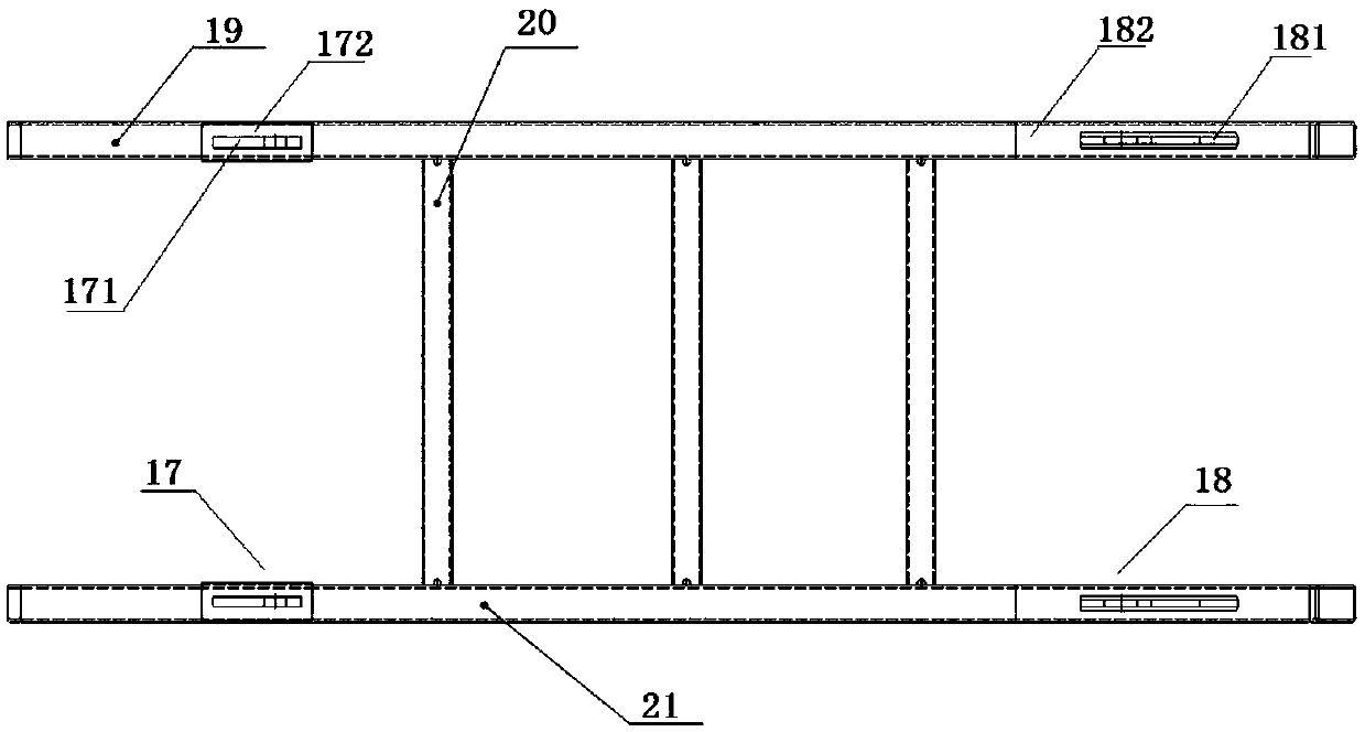
technical field [0001] The invention relates to a welding positioning device for a connecting seat. Background technique [0002] The bottom frame of the existing pure electric self-loading garbage truck needs to weld the connecting seat for the scraper to connect. The structure of the connecting seat is as follows: figure 1 with figure 2 As shown, the connecting seat includes the right base plate 19 of the connecting seat, the left base plate 21 of the connecting seat and the scraper oil cylinder seat welding 17 and the cylinder connecting seat welding 18 respectively arranged on the right base plate 19 of the connecting seat and the left base plate 21 of the connecting seat. The scraper cylinder seat welding 17 includes the scraper hinged lug 171 and the scraper connecting bottom plate 172 vertically arranged with the scraper hinged lug 171, and the oil cylinder connection seat welding 18 includes the cylinder seat hinged lug 181 and the cylinder seat hinged ear. Plate ...

Claims


Application Information

Patent Timeline
Patent Type & Authority Applications(China)
IPC IPC(8): B23K37/04
CPCB23K37/0426
Inventor 梁九艳吕振伟楚金甫李柯曾艳昆杨阳
Owner HENAN BENMA
Learn More