
Vision-based large vehicle dead zone monitoring device

A blind spot monitoring and vehicle technology, which is applied to signal devices, vehicle components, sound signal devices, etc., can solve the problems of difficulty in looking around equipment, inability to use vehicles, and the rear inner wheel driving off the road, so as to avoid driving hazards and do not require professional installation. , the effect of increasing the safety distance

Pending Publication Date: 2020-04-21
天津布尔科技有限公司
View PDF8 Cites 1 Cited by
  • Summary
  • Abstract
  • Description
  • Claims
  • Application Information

AI Technical Summary

Problems solved by technology

If you only pay attention to the passage of the front wheels and forget the difference between the inner wheels during driving, it may cause accidents where the rear inner wheels drive off the road or collide with other objects
[0008] Ultrasonic radar is a short-distance ranging radar, and its measurement range is small, so it is difficult to use it on large vehicles with long distances; ultrasonic radar is limited by quantity and performance, and cannot be installed in large quantities; the surround view solution is mostly used for vehicle parking, only in the vehicle It is effective in a relatively close range; it is difficult for surround view equipment to predict fast-moving and random vehicles and pedestrians in time; surround view pays more attention to parking assistance, and performs well at extremely low speeds, so it cannot be applied to driving vehicles

Method used


Image

  • Vision-based large vehicle dead zone monitoring device
  • Vision-based large vehicle dead zone monitoring device
  • Vision-based large vehicle dead zone monitoring device

Examples


Embodiment 1

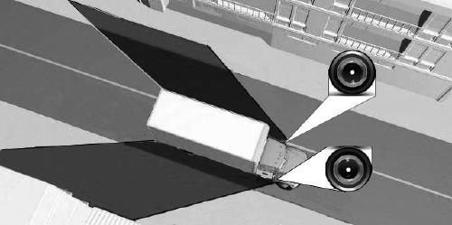
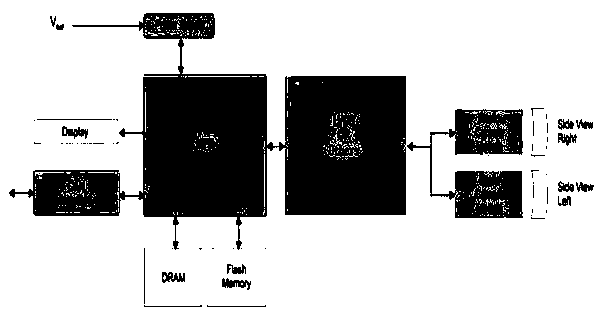
[0028] A vision-based large-scale vehicle blind spot monitoring device, which consists of: a car, the car is connected to a cardan shaft, the cardan shaft is connected to a camera, the camera is connected to a data line, and the data line is connected to a smart phone algorithmic controller.

[0029] The camera is set under the rearview mirror of the car or at any position where no occlusion occurs on both sides of the car; the camera is a wide-angle camera.

Embodiment 2

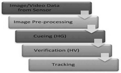
[0031] A vision-based large-scale vehicle blind spot monitoring device described in Embodiment 1, the visual data frame of the camera is transmitted to the intelligent algorithm controller through the data line, and in the intelligent algorithm controller, the visual data is analyzed by the corresponding visual algorithm Frame images are analyzed to find and track potential targets of pedestrians, motor vehicles, bicycles, motorcycles and other objects in the images that may collide with the doors; at high frame rates, each frame of image data is efficiently calculated to ensure the results Real-time, and at the same time calculate the distance and speed of each potential target that may collide with the door and the vehicle, and draw up a safety threshold for distance and speed. When the distance or speed of no potential target exceeds the safety threshold, the intelligent algorithm controller It is considered safe to open the door at this time, otherwise it is considered unsa...

Embodiment 3

[0033] In the blind spot monitoring device for large-scale vehicles based on vision described in Embodiment 2, the intelligent algorithm controller is connected to the sound and light alarm through the power line and the control line, and uses the vehicle control system to obtain the steering wheel operation information of the vehicle; when the intelligent algorithm When the controller judges that the driver is operating the steering wheel to turn, if there is a vehicle or person on the side of the car that is dangerously far away from the blind spot, it will actively trigger an audible and visual alarm to remind the driver of a potential dangerous situation and indicate which side has the dangerous situation; After the danger is removed, the alarm disappears.


PUM


Abstract

The invention discloses a vision-based large vehicle dead zone monitoring device which comprises an automobile; the automobile is connected with a cardan shaft, the cardan shaft is connected with a camera, the camera is connected with a data line, and the data line is connected with an intelligent algorithm controller. The vision-based large vehicle dead zone monitoring device is used for monitoring dead zones of large vehicles.

Description

Technical field: [0001] The invention relates to a blind spot monitoring device for large vehicles based on vision. Background technique: [0002] At present, the existing large-scale vehicle blind spot monitoring schemes on the market generally use ultrasonic radar schemes and vehicle surround view schemes. [0003] The ultrasonic wave installed at the rear of the vehicle can capture objects close to the rear of the vehicle, and is generally used for reversing assistance. Ultrasonic radar is a short-distance ranging radar with a small measurement range. It is used in domestic passenger cars and can be used for parking assistance. However, when used in large vehicles, it is only selectively installed in local locations of the vehicle, subject to the quantity and Due to performance limitations, objects in the blind area can only be detected at a specific and relatively close position, and the shape and specific information of the object cannot be distinguished, and the exist...

Claims


Application Information

Patent Timeline
IPC IPC(8): B60R1/00B60Q5/00
CPCB60R1/00B60Q5/005B60R2300/105B60R2300/802
Inventor 闫方超刘畅
Owner 天津布尔科技有限公司
Learn More