
Light-based lane-change control

A technology for lane changing and roadside infrastructure, applied in the direction of non-electric variable control, services based on specific environments, control devices, etc., can solve the problem of inability to predict the movement of other vehicles or future paths with certainty

Pending Publication Date: 2020-04-21
FORD GLOBAL TECH LLC
View PDF0 Cites 0 Cited by
  • Summary
  • Abstract
  • Description
  • Claims
  • Application Information

AI Technical Summary

Problems solved by technology

Conventional on-board sensor sets (e.g., cameras, radar, LIDAR, etc.) cannot predict the motion or future paths of other vehicles with a high degree of certainty

Method used


Image

  • Light-based lane-change control
  • Light-based lane-change control
  • Light-based lane-change control

Examples


Embodiment Construction

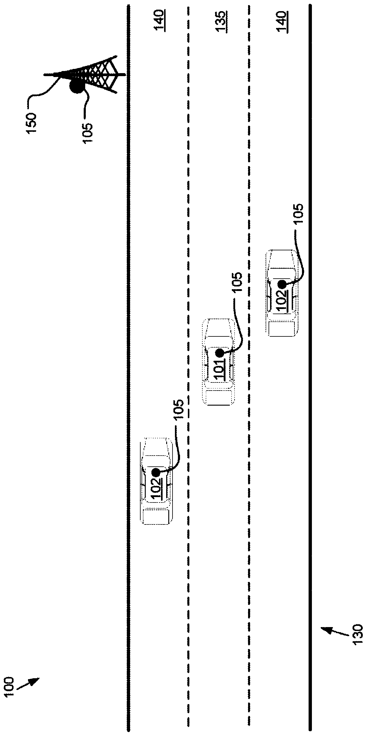
[0010] figure 1 is a diagram of an exemplary vehicle-to-vehicle light-based communication system 100 . The first vehicle 101 and the one or more second vehicles 102 may travel in the same direction on respective lanes 135 , 140 of the road 130 . Each vehicle 101, 102 and infrastructure element 150 may have a light-based communication transceiver 105 mounted thereon. The infrastructure element 150 may update the security credentials maintained by each vehicle 101, 102 from time to time. Upon determining to change lanes, vehicle 101 may initiate light-based communication with one or more other vehicles 102 . Security certificates may be used to authenticate light-based communications. After the vehicles 101 , 102 have confirmed the authenticity and safety of the light-based communication, then communications between the vehicles 101 , 102 may include communications for negotiating and / or planning a lane change of the vehicle 101 .

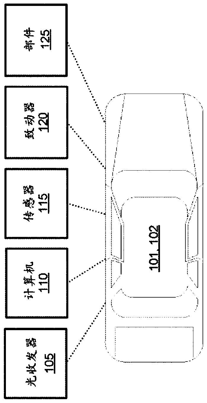
[0011] figure 2 is a block diagram of an...


PUM


Abstract

The invention provides light-based lane-change control. Upon a determination to execute a lane change, a light-based request communication, including a security key, can be sent to a target vehicle tonegotiate the lane change. Upon receiving a light-based response communication from the target vehicle, the lane change can be executed.

Description

technical field [0001] The present disclosure generally relates to vehicle steering and control. Background technique [0002] For vehicles, especially autonomous vehicles, being able to change lanes without experiencing a collision or creating an unacceptable risk of collision is a challenging problem. This is true regardless of whether the vehicles in adjacent lanes are operated by computers or humans. Conventional on-board sensor sets (e.g., cameras, radar, LIDAR, etc.) cannot predict the motion or future paths of other vehicles with a high degree of certainty. Contents of the invention [0003] A system may include a computer including a processor and a memory storing instructions executable by the processor to send a light-based message including a security key to a target vehicle when it is determined that a lane change is to be performed. communicating a request to negotiate the lane change; and upon receiving a light-based response communication from the target v...

Claims


Application Information

Patent Timeline
Patent Type & Authority Applications(China)
IPC IPC(8): B60W30/18H04L29/08H04L29/06H04L9/08H04L9/32H04W4/40H04W4/44H04W4/46B60W50/00
CPCB60W30/18163H04L67/12H04L63/0823H04L9/3247H04L9/0838H04W4/40H04W4/44H04W4/46B60W50/00H04L2209/84H04L9/3263H04L9/0891G08G1/167G08G1/096741G08G1/096708G08G1/096791G08G1/162G05D1/0276H04L9/3268B60W2556/45
Inventor 张琳军海伦·伊丽莎白·库鲁斯-哈里根
Owner FORD GLOBAL TECH LLC
Learn More