Supercharge Your Innovation With Domain-Expert AI Agents!

Automatic chain plate cleaning device

An automatic cleaning and chain plate technology, which is applied in cleaning devices, transportation and packaging, cleaning methods and utensils, etc., can solve serious problems such as chain plate sticking, hole blocking, etc.

Pending Publication Date: 2020-04-21
百特(福建)智能装备科技有限公司
View PDF0 Cites 0 Cited by
  • Summary
  • Abstract
  • Description
  • Claims
  • Application Information

AI Technical Summary

Problems solved by technology

[0003] The invention provides a device for automatic cleaning of chain plates, which aims to solve the problem of serious sticky materials on chain plates and even block holes, and improve the efficiency of airing

Method used


Image

  • Automatic chain plate cleaning device
  • Automatic chain plate cleaning device
  • Automatic chain plate cleaning device

Examples


Embodiment 1

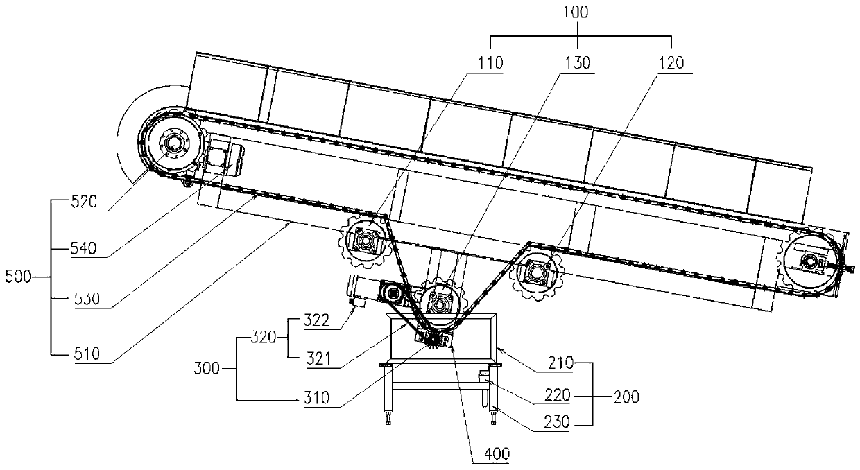
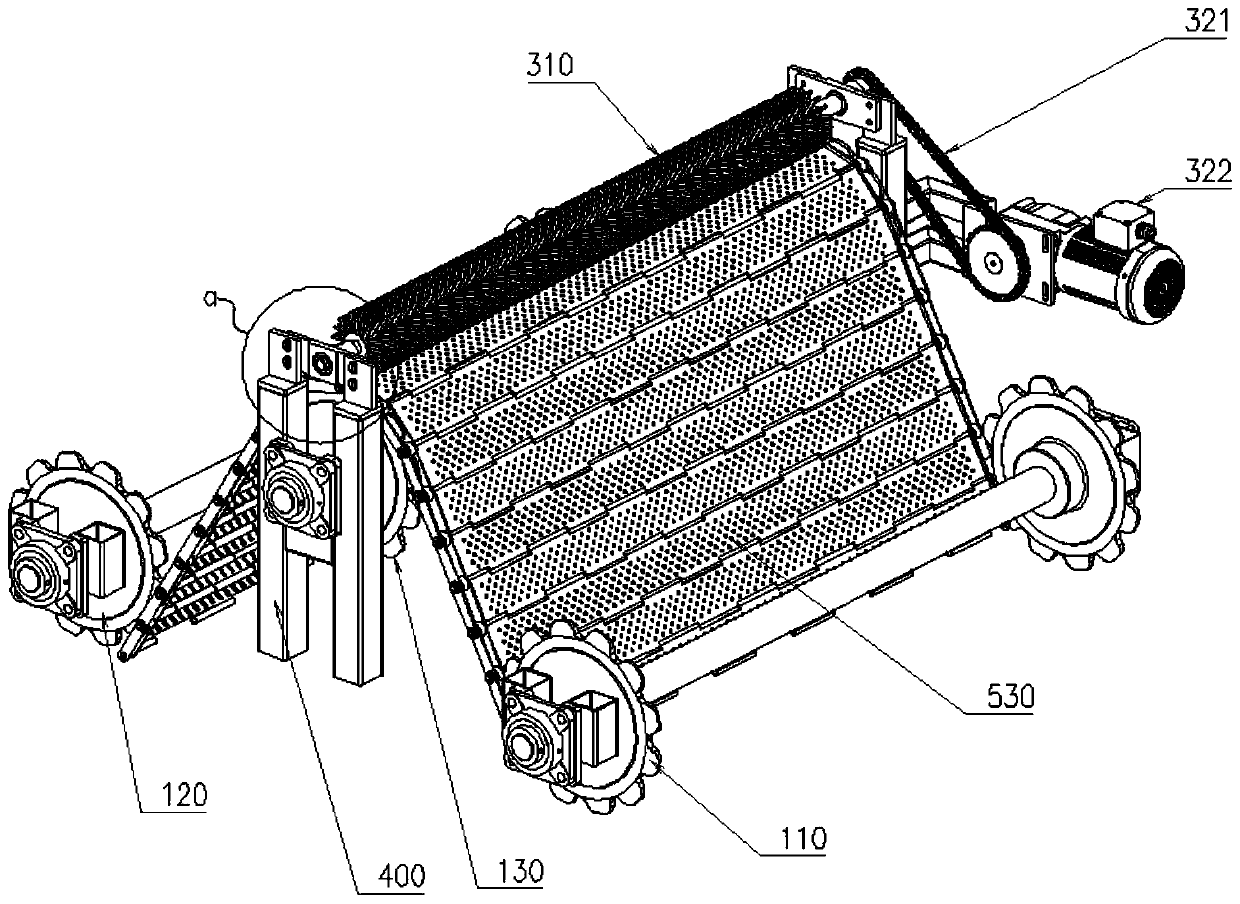
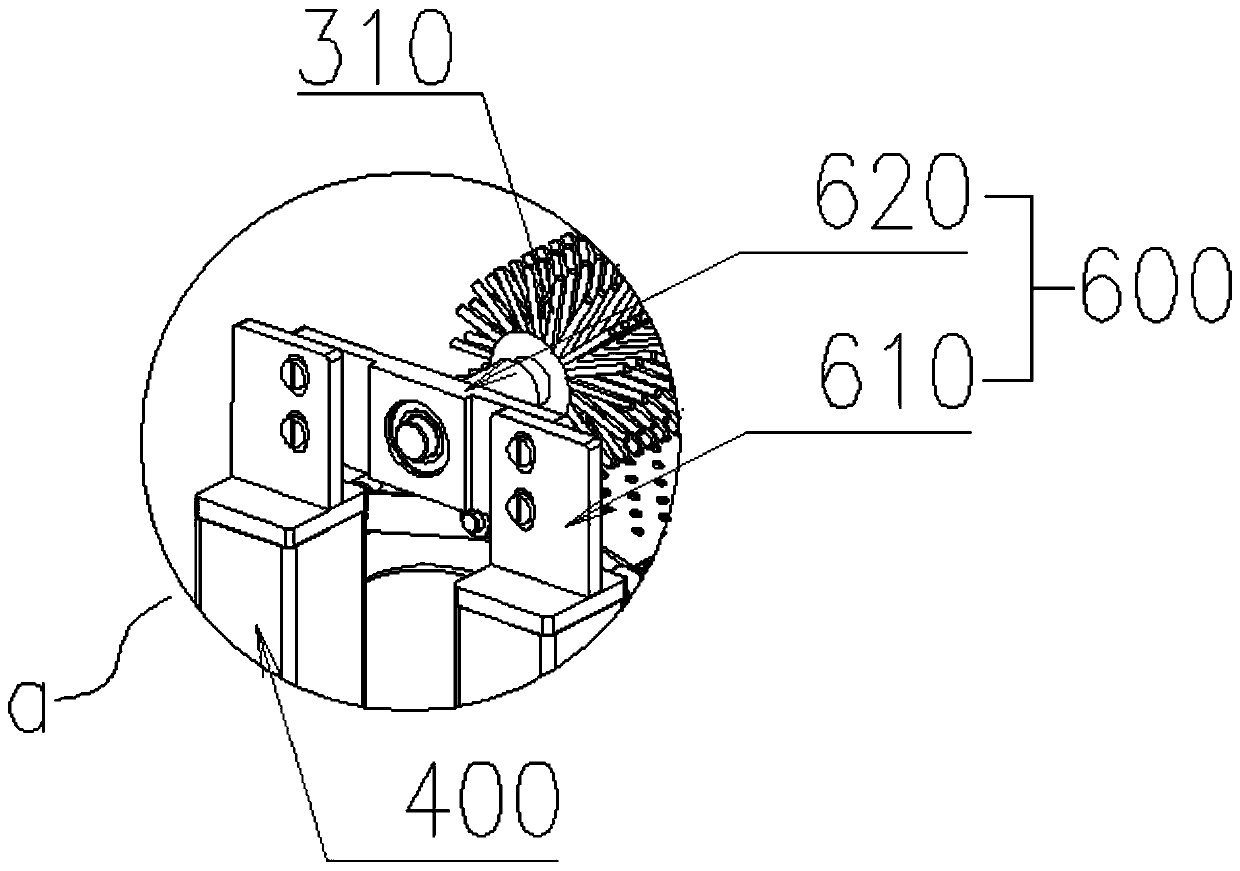
[0031] refer to Figure 1-4 As shown, a chain plate automatic cleaning device is installed below the parallel chain plate machine 500, which includes: a chain plate bias mechanism 100, a water tank assembly 200, a brush roller mechanism 300 and a fixing frame 400;

[0032] Wherein the parallel chain plate machine 500 is a conventional parallel chain plate machine, which includes a parallel chain plate frame body 510, a sprocket wheel 520 rotatably connected to both sides of the parallel chain plate frame body 510, and a parallel chain wheel wound between the sprocket wheels 520 on both sides. The chain plate 530 of the chain plate machine and the reduction motor 540 for driving the rotation of the sprocket 520; when the parallel chain plate machine 500 starts, the reduction motor 540 drives the chain plate 530 of the parallel chain plate machine through the sprocket 520 for transmission.

[0033] The fixed frame 400 has two groups symmetrically fixed on the front and rear side...

Embodiment 2

[0046] It is basically the same as Embodiment 1, except that the driving mechanism 320 includes a sprocket coaxially fixedly installed on the end of the same side of the third sprocket set 130 and the brush roller assembly 310 and a chain installed between the two sets of sprockets (not shown in the figure); that is, the third group of sprockets 130 provides rotational power to the brush roller assembly 310 through chain transmission.

Embodiment 3

[0048] It is basically the same as Embodiment 1, except that the driving mechanism 320 includes a pulley coaxially fixedly installed on the end of the same side of the third sprocket set 130 and the brush roller assembly 310 and a belt installed between the two sets of pulleys (Fig. not shown in); that is, the third group of sprockets 130 provides rotational power to the brush roller assembly 310 through belt transmission.


PUM


Abstract

The invention relates to the field of white wine automatic production, in particular to an automatic chain plate cleaning device. The automatic chain plate cleaning device is mounted below a parallelchain plate machine and comprises a chain plate offset mechanism, a water groove assembly, a brush roller mechanism and fixed frames, the two fixed frames are symmetrically fixed to the front side andthe rear side of the bottom of a parallel chain plate machine frame body, the chain plate offset mechanism comprises a first chain wheel set, a second chain wheel set and a third chain wheel set, thefirst chain wheel set and the second chain wheel set are located on the left sides and the right sides of the fixed frames, and are rotatably mounted on the parallel chain plate machine frame body, achain plate of the parallel chain plate machine winds around the third chain wheel set, and teeth on the first chain wheel set, the second chain wheel set and the third chain wheel set are engaged into chain structures on the two sides of the chain plates of the parallel chain plate machine. According to the automatic chain plate cleaning device, serious sticking and even hole blocking of the chain plate can be solved, and the distilled grain spread airing efficiency can be improved.

Description

technical field [0001] The invention relates to the field of liquor automatic production, in particular to an automatic chain plate cleaning device. Background technique [0002] In the production of liquor, some fermented grains are spread and dried, and some spreaders with perforated stainless steel chain plates are used. A lot of small holes are evenly distributed on the chain plate, and the cold air passes through the small holes on the chain plate to directly air the bad grains to cool down. During the airing process, the gelatinized starch of the chain plate with holes will stick to the surface of the chain plate or even block the holes, which cannot be cleaned with ordinary scrapers or brushes, resulting in the reduction of airing efficiency and airing effect . On-line cleaning of the chain plate will eliminate the blocking of holes on the chain plate and ensure the smooth progress of spreading. Contents of the invention [0003] The invention provides an automat...

Claims


Application Information

Patent Timeline
IPC IPC(8): B65G45/24B65G21/20C12G3/02B08B1/02B08B3/04
CPCB65G45/24B65G21/2045C12G3/02B08B3/041B08B1/12B08B1/20
Inventor 陈钦明肖正宗徐中福刘海金林家麟
Owner 百特(福建)智能装备科技有限公司
Features
  • R&D
  • Intellectual Property
  • Life Sciences
  • Materials
  • Tech Scout
  • Unparalleled Data Quality
  • Higher Quality Content
  • 60% Fewer Hallucinations
Learn More