
Side wall conveying transmission system

A transmission system and conveyor line technology, applied in the direction of lifting devices, etc., can solve the problems of conveyor line assembly, commissioning and maintenance difficulties, etc., and achieve the effects of simple installation, commissioning and maintenance, ensuring synchronization, and improving force

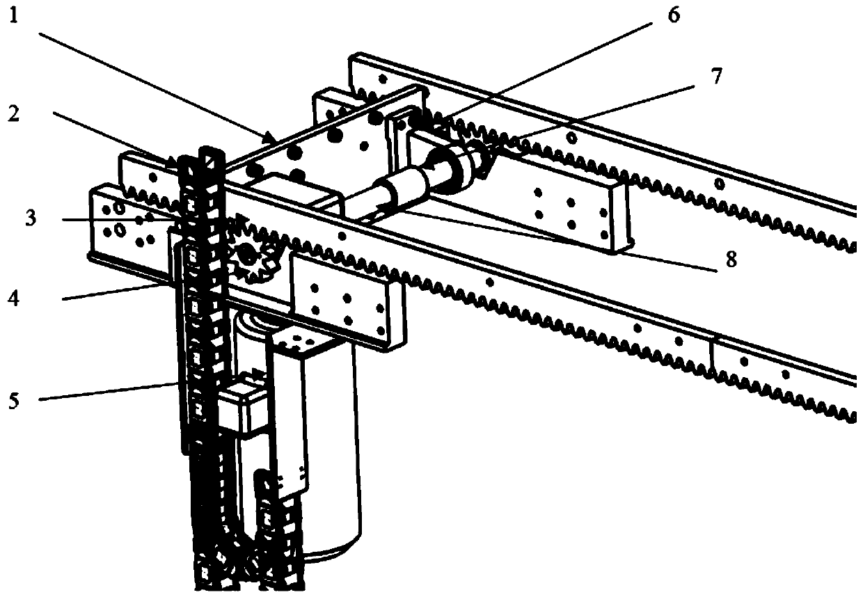
Inactive Publication Date: 2020-04-21
SAIC-GM-WULING AUTOMOBILE CO LTD
View PDF5 Cites 2 Cited by
  • Summary
  • Abstract
  • Description
  • Claims
  • Application Information

AI Technical Summary

Problems solved by technology

In the existing mechanism, the motor assembly is located in the middle of the conveyor line, and the assembly, debugging and maintenance of the conveyor line are very difficult

Method used


Image

  • Side wall conveying transmission system
  • Side wall conveying transmission system
  • Side wall conveying transmission system

Examples


Embodiment Construction

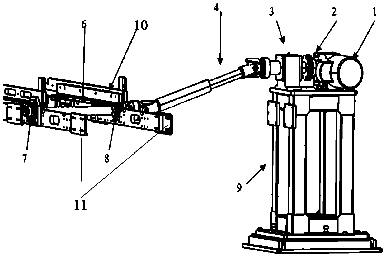
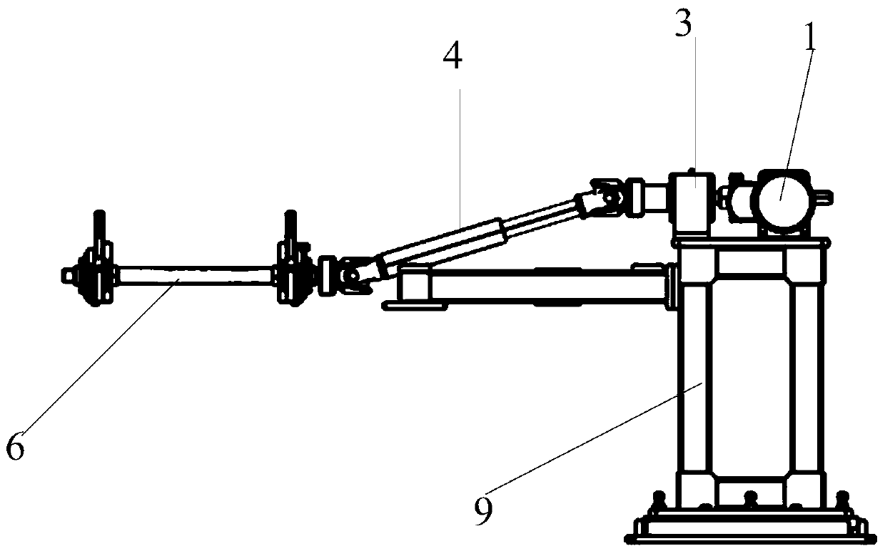
[0021] Such as Figure 2-7 As shown, the present invention discloses a side circumference conveying transmission system, including a driving mechanism, a linkage mechanism, a telescopic universal joint 4, and a conveying line mechanism. The conveying line mechanism includes a conveying line driving mechanism, a transmission shaft 6, and the The driving mechanism is connected with the linkage mechanism, the linkage mechanism is connected with the telescopic universal joint 4, the telescopic universal joint 4 is connected with the transmission shaft 6, and the transmission shaft 6 is installed on the conveying On the line drive mechanism, the drive mechanism drives the linkage mechanism, the telescopic universal joint 4, and the transmission shaft 6 to rotate in turn, and the transmission shaft 6 drives the transmission line drive mechanism to move through rotation; when the When the transmission line mechanism reciprocates up and down, the transmission shaft 6 is in the process...


PUM


Abstract

The invention provides a side wall conveying transmission system. The system comprises a driving mechanism, a linkage mechanism, a telescopic universal joint and a conveying line mechanism, the conveying line mechanism comprises a conveying line driving mechanism and a transmission shaft; the driving mechanism is connected with the linkage mechanism, the linkage mechanism is connected with the telescopic universal joint, the telescopic universal joint is connected with the transmission shaft, the transmission shaft is installed on the conveying line driving mechanism, the driving mechanism sequentially drives the linkage mechanism, the telescopic universal joint and the transmission shaft to rotate, and the transmission shaft drives the conveying line driving mechanism to move through rotation. When the conveying line mechanism reciprocates up and down, the telescopic universal joint can automatically adjust the distance between the transmission shaft and the linkage mechanism in the process that the transmission shaft ascends and descends along with the conveying line mechanism. The side wall conveying transmission system has the beneficial effects that 1, a motor of the side wallconveying transmission system is fixed outside the conveying line, and the motor is simple to install, debug and maintain; and 2, gear racks at the two sides of the side wall conveying transmission system are transmitted through one transmission shaft, and conveying synchronism is guaranteed.

Description

technical field [0001] The invention relates to the field of automobile assembly, in particular to a side wall conveying transmission system. Background technique [0002] The side wall conveying system currently used by SGMW is in the form of a reciprocating rod. The synchronous rack and pinion ensures the lifting synchronization of the conveyor line, and the conveying motor drives the rack and pinion to realize the conveying of the side wall. In the existing mechanism, the motor assembly is located in the middle of the conveying line, and the assembly, debugging and maintenance of the conveying line are very difficult. [0003] structure as background figure 1 Shown: [0004] 1 motor mounting plate; 2 drag chain; 3 rack; 4 gear; 5 motor; 6 bearing seat; 7 coupling; 8 transmission shaft. Contents of the invention [0005] The invention provides a transmission transmission system for side circumference, which includes a driving mechanism, a linkage mechanism, a telescop...

Claims


Application Information

Patent Timeline
Patent Type & Authority Applications(China)
IPC IPC(8): B66F11/00B66F13/00
CPCB66F11/00B66F13/00
Inventor 张涛蒙文范刘参参许丽虹冯志鹏
Owner SAIC-GM-WULING AUTOMOBILE CO LTD
Learn More