Supercharge Your Innovation With Domain-Expert AI Agents!

Rear-mounted thin-wall steel pipe water drainage device and method for large bottom plate anti-floating

A thin-walled steel pipe, rear-mounted technology, used in protection devices, buildings, infrastructure projects, etc., can solve the problems of high economic cost and many construction procedures, and achieve the effect of saving economic costs, optimizing construction procedures and saving costs.

Pending Publication Date: 2020-04-21
SHANGHAI NO 7 CONSTR
View PDF0 Cites 0 Cited by
  • Summary
  • Abstract
  • Description
  • Claims
  • Application Information

AI Technical Summary

Problems solved by technology

However, the economic cost of this method is higher, and the construction process is more

Method used


Image

  • Rear-mounted thin-wall steel pipe water drainage device and method for large bottom plate anti-floating
  • Rear-mounted thin-wall steel pipe water drainage device and method for large bottom plate anti-floating

Examples


Embodiment Construction

[0032] The present invention will be described in further detail below in conjunction with the accompanying drawings and specific embodiments. The technical content and features of the present invention will be described in detail below by referring to the illustrated embodiments in conjunction with the accompanying drawings. It should be further noted that all the drawings are in very simplified form and use imprecise scales, and are only used to facilitate and clearly assist the purpose of illustrating the embodiments of the present invention. For the convenience of description, the "up" and "down" described below are consistent with the directions of up and down in the drawings, but this should not be a limitation of the technical solution of the present invention.

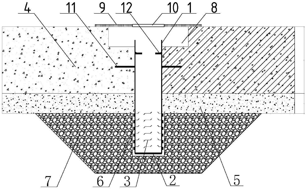
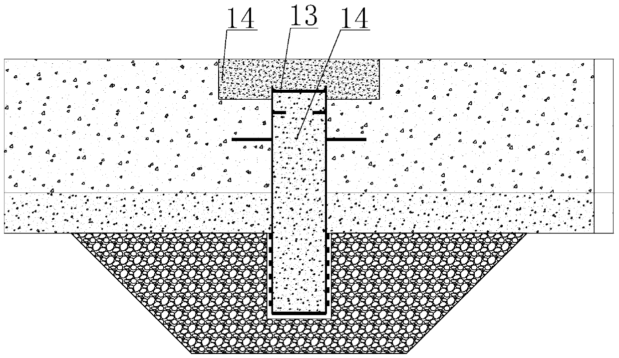
[0033] see Figure 1 to Figure 2 , this embodiment discloses a post-mounted thin-walled steel pipe drainage device for anti-floating of large bottom plates, including a steel pipe 1, a bottom sealing plate 2 a...


PUM


Abstract

The invention discloses a rear-mounted thin-wall steel pipe water drainage device and method for large bottom plate anti-floating. A steel pipe, a bottom sealing plate and a filter screen are adopted,wherein the upper end of the steel pipe is positioned in a bottom plate in a penetrating mode; the lower part of the steel pipe penetrates through a base plate and extends into a pit groove positioned below the base plate; water permeable filler is arranged in the pit groove; the filter screen is arranged on the outer side of the pipe section, extending into the pit groove, of the steel pipe; a plurality of holes are formed in the pipe section, extending into the pit groove, of the steel pipe; the bottom sealing plate is arranged at the bottom of the pipe section, extending into the pit groove, of the steel pipe; the top of the steel pipe is positioned below the upper surface of the bottom plate; a groove is reserved in the bottom plate; a cover plate used for sealing the groove is arranged on the bottom plate; a through hole used for containing a pump pipe of a drainage pump is formed in the cover plate; and the through hole can cover the steel pipe. Underground water below a cushionlayer can sequentially pass through the pit groove and the filter screen to flow into the steel pipe, and therefore the length needed by the steel pipe is much smaller than the length of a vacuum pipe well additionally arranged in the foundation pit dewatering stage, and the cost is saved on the premise that the anti-floating requirement is met.

Description

technical field [0001] The invention relates to the anti-floating technical field of the bottom plate in the construction stage, in particular to a rear-mounted thin-walled steel pipe drainage device and method for anti-floating of a large bottom plate. Background technique [0002] In the actual foundation pit dewatering construction process, light well point dewatering wells are often used. At the same time, the groundwater is relatively abundant, and the excavation continues, the light well point dewatering wells will be gradually pulled out, and the cushion and floor construction will continue to follow up, resulting in The buoyancy of the groundwater under the bottom plate is continuously increasing. [0003] In order to ensure that the bottom plate does not float up, a weep hole is added. If a vacuum tube well is added during the dewatering stage of the foundation pit, the part of the vacuum tube well higher than the elevation of the floor top will be cut off after th...

Claims


Application Information

Patent Timeline
Patent Type & Authority Applications(China)
IPC IPC(8): E02D31/12E02D31/02E02D19/10
CPCE02D31/12E02D31/02E02D19/10
Inventor 卢良志陆秋平冯德亮周吉方思倩
Owner SHANGHAI NO 7 CONSTR
Features
  • R&D
  • Intellectual Property
  • Life Sciences
  • Materials
  • Tech Scout
  • Unparalleled Data Quality
  • Higher Quality Content
  • 60% Fewer Hallucinations
Learn More