Garbage vertical discharge device for building high-rise

A discharge device and garbage technology, which is applied in the direction of buildings, building components, building structures, etc., can solve the problems of pipeline impact damage, large impact force, large construction waste and dust, etc.

Active Publication Date: 2020-04-21
临沂产业研究院有限公司
View PDF5 Cites 5 Cited by
  • Summary
  • Abstract
  • Description
  • Claims
  • Application Information

AI Technical Summary

Problems solved by technology

[0004] 1. When the high-level is throwing garbage, the low-level also has garbage thrown at the same time, so that the high-level garbage hits the low-level garbage in the process of falling, and the high-level sliding has a greater impact force, which will generate a greater impact force. impact damage to lower pipes
[0005] 2. When the construction waste is thrown down, it will be thrown together with the dust. When the solid block of construction waste is placed at the bottom position, the impact force between it and the parts will blow up the dust by the way. and the dust of construction waste is relatively large, which is difficult to dissipate

Method used


Image

  • Garbage vertical discharge device for building high-rise
  • Garbage vertical discharge device for building high-rise
  • Garbage vertical discharge device for building high-rise

Examples


Embodiment 1

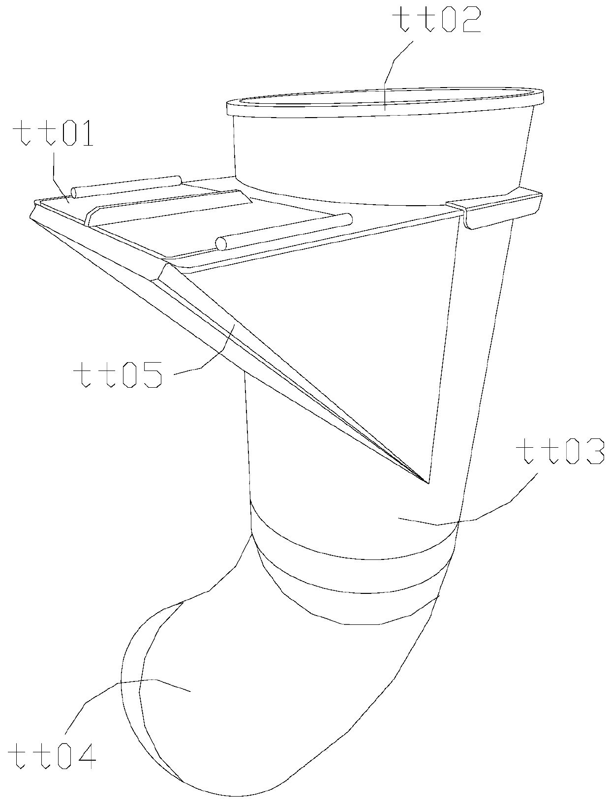
[0032] as attached figure 1 to attach Figure 5 Shown:

[0033] The invention provides a vertical discharge device for building high-rise garbage, the structure of which includes an insertion inlet tt01, an upper connection guide outlet tt02, a middle pipe tt03, an arc relief outlet tt04, and an auxiliary inlet tt05.

[0034] The insertion port tt01 and the auxiliary port tt05 are integrated structures, the upper connection guide port tt02 is welded above the middle tube tt03, and the end of the middle tube tt03 away from the upper connection guide port tt02 is connected to the arc buffer port tt04.

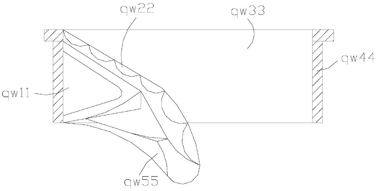
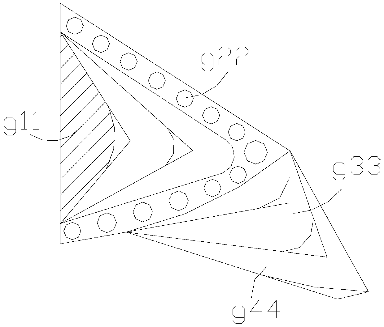
[0035] Wherein, the upper connection guide port tt02 includes a stabilizing force angle qw11, a large surface arc qw22, a central tube qw33, an outer limiting shell qw44, and a swing core qw55, and the stabilizing force angle qw11 is against the outer surface of the large surface arc qw22. The large surface arc qw22 is connected with the swing core qw55, the middle tube qw33 is...

Embodiment 2

[0042] as attached Figure 6 to attach Figure 8 Shown:

[0043] Wherein, the arc buffer port tt04 includes a middle buffer tube hh1, an outer layer hh2, a core impact angle hh3, and a force isolation angle hh4. The center buffer tube hh1 is installed inside the outer layer hh2, and the force isolation angle hh4 conflicts with On the outer surface of the core attack angle hh3, the force isolation angle hh4 is distributed at intervals with the connecting parts, the core attack angle hh3 is evenly distributed in an arc shape, the outer support layer hh2 controls the range of the inner road, and the force isolation angle hh4 allows The connecting parts have a certain resistance to the fixed interval force, the core impact angle hh3 bears the external impact, gathers it to press inward, and the middle buffer tube hh1 allows the object to move smoothly.

[0044] Wherein, the core punching angle hh3 includes the punching surface tr11, the middle support bar tr22, the punching angl...


PUM


Abstract

The invention discloses a garbage vertical discharge device for a building high-rise. The device structurally comprises an inlet, an upper connecting guide port, a middle pipe and an arc buffer port,wherein the inlet and an auxiliary inlet are of an integrated structure; when building garbage falling down along a middle cylinder above the inlet slides through the inlet, the building garbage can firstly abut against an abutting surface, and force is converged on the abutting surface to be released; when a large surface arc bears impact force, unfolding corners form proper stretching and protection, garbage above can turn with a certain radian when garbage above and garbage below are placed at the same time, and then the garbage above is prevented from colliding with the garbage below; theinternal space of a middle buffer cylinder is limited by a core impact corner protruding inwards, so that force is released towards a middle support strip inside, the abutting impact force can be applied together along a top guard head, the garbage is conveyed out after the impact force is reduced, an outlet can be limited when the building garbage is about to be discharged out of the device, andtherefore the garbage is discharged after impact buffering.

Description

technical field [0001] The invention belongs to the construction field, and more specifically relates to a vertical discharge device for building high-rise garbage. Background technique [0002] When a multi-storey building is in the process of construction, there will be a lot of construction waste such as stones and lime, and the construction waste pipes will be installed between the floors and the outside, so that it can throw construction waste into the pipes at the upper level, so that it can be smoothly Follow the guidance of the pipe to the bottom ground for throwing. [0003] Based on the inventor's discovery above, existing construction waste discharge devices mainly have the following deficiencies, such as: [0004] 1. When the high-level is throwing garbage, the low-level also has garbage thrown at the same time, so that the high-level garbage hits the low-level garbage in the process of falling, and the high-level sliding has a greater impact force, which will g...

Claims


Application Information

Patent Timeline
Patent Type & Authority Applications(China)
IPC IPC(8): E04F17/10E04F17/12
CPCE04F17/10E04F17/12
Inventor 李成玉
Owner 临沂产业研究院有限公司
Why Eureka
Try Eureka