Wave energy eliminating structure of drifting buoy

A drifting buoy and wave energy technology, applied in the direction of buoys, ships, special-purpose ships, etc., can solve the problems of affecting buoys, destroying photovoltaic panels, ship collisions, etc., to achieve the effect of reducing friction and avoiding left and right shaking

Active Publication Date: 2020-04-21
湖南省池海浮标钓具有限公司
View PDF9 Cites 5 Cited by
  • Summary
  • Abstract
  • Description
  • Claims
  • Application Information

AI Technical Summary

Problems solved by technology

[0003] 1. Since the drifting buoy floats in the ocean with the wind and current, accidents of ships hitting the buoy and the buoy itself hitting reefs and drifting objects often occur. Although the anti-collision plate 2 will reduce the damage to the buoy caused by the impact, the vibration caused by the impact It will still affect the buoy, and the larger vibration and shaking will affect the internal equipment of the buoy, which will not only cause the internal equipment of the buoy to loosen, but also violent vibration will damage the photovoltaic panels 6 and lamps installed around the fixed bracket 5

Method used


Image

  • Wave energy eliminating structure of drifting buoy
  • Wave energy eliminating structure of drifting buoy
  • Wave energy eliminating structure of drifting buoy

Examples


Embodiment 1

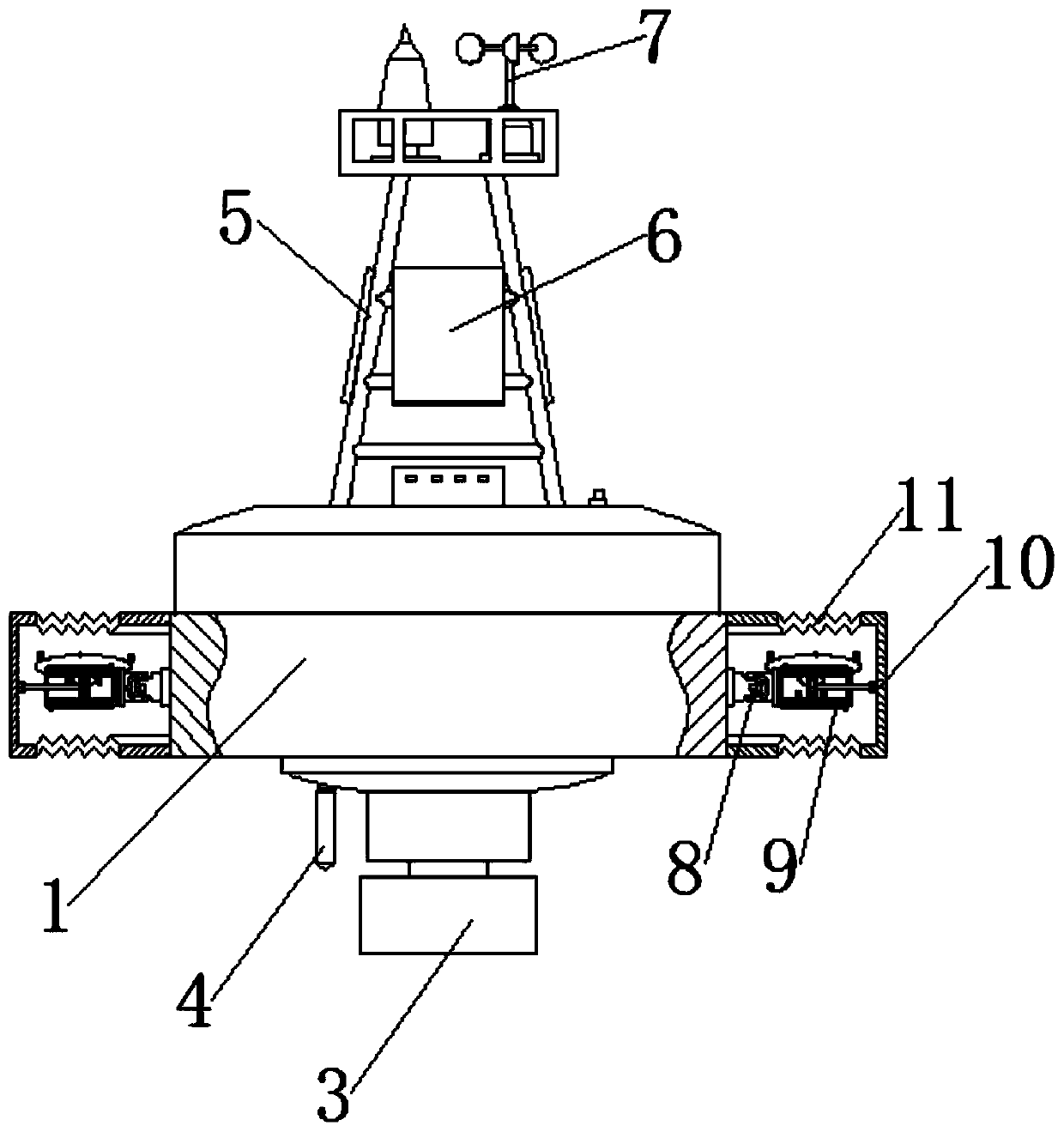
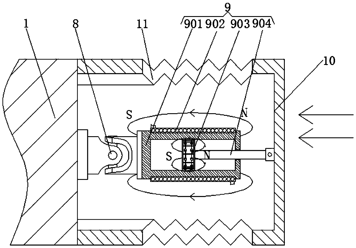
[0032] see Figure 1-11 , a structure for eliminating sea wave energy of a drifting buoy, comprising a buoy body 1, the side of the buoy body 1 is fixedly connected with an anti-collision plate 2, the middle part of the bottom end of the buoy body 1 is fixedly connected with a counterweight 3, and one side of the bottom of the buoy body 1 The hydrological observation equipment 4 is fixedly installed, and the upper part of the buoy body 1 is fixedly welded with a fixed bracket 5, and the sides of the fixed bracket 5 are fixedly installed with a photovoltaic panel 6, and the upper part of the fixed bracket 5 is fixedly installed with a meteorological observation equipment 7, and the buoy body 1 The middle part of the outside of the housing is fixedly connected with four universal joints 8 arranged in equal circles, and the other ends of the four universal joints 8 are fixedly connected with electromagnetic energy dissipating devices 9, and the other ends of the four electromagnet...

Embodiment 2

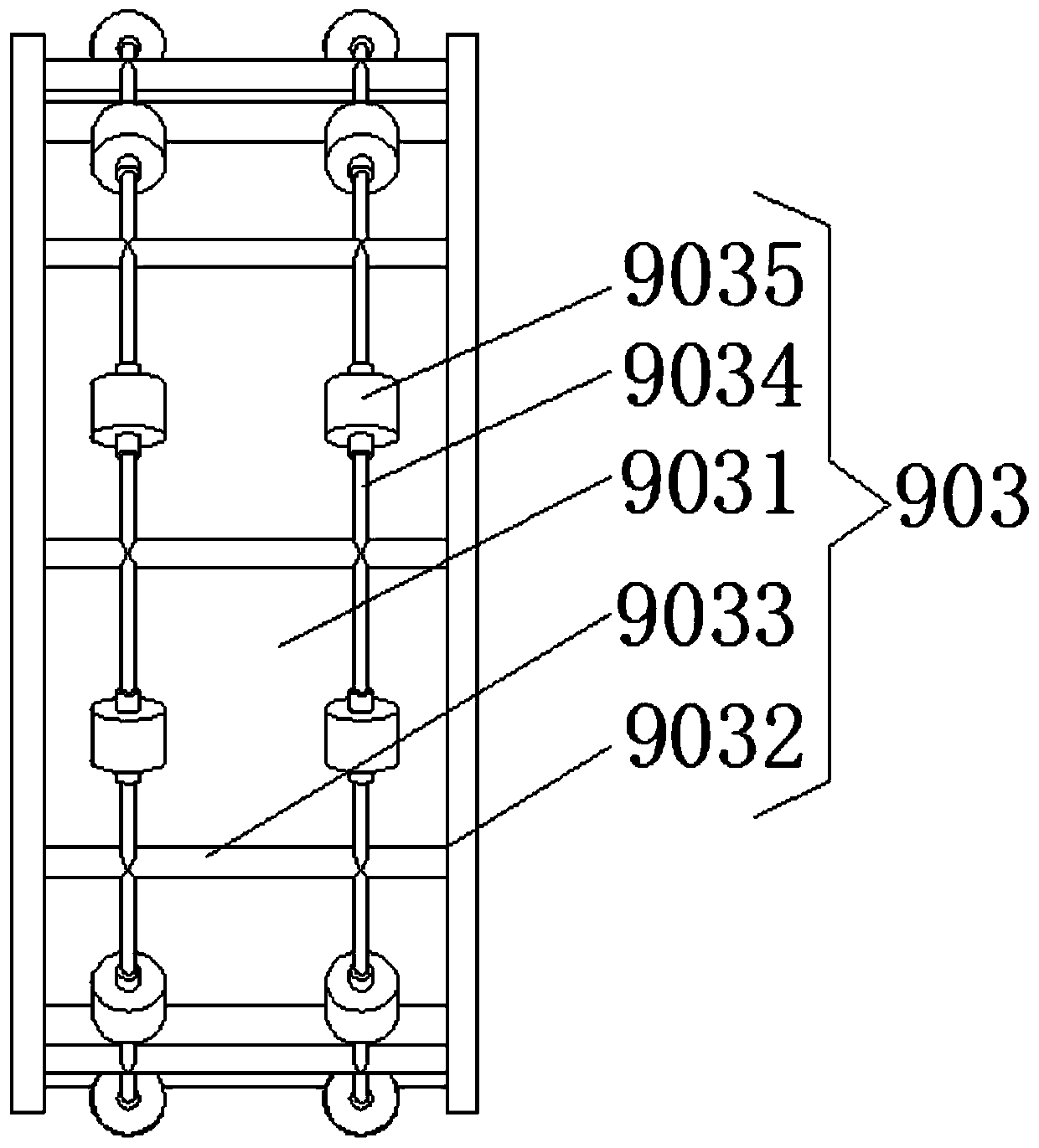
[0039] Different from Embodiment 1, refer to Figure 11-13 , wherein the outer side of the coil 902 can also be fixedly installed with a smooth insulating sleeve 12, the upper end of the smooth insulating sleeve 12 is fixedly connected with a resistance block 13, and the outer side of the smooth insulating sleeve 12 is movably connected with a circular sliding sleeve 14, and the circular sliding sleeve The upper part of the inner side of 14 is provided with the chute that matches with resistance block 13, and the inside of circular sliding sleeve 14 chutes is fixedly installed with conductive block 15, and the outer side of circular sliding sleeve 14 is fixedly connected with four equicircumferential arrangements. four support frames 16, and the other ends of the four support frames 16 are all fixedly connected with the sides at the two ends of the connecting rod 904, as Figure 12 As shown, when the connecting rod 904 is forced to move to the left in the cylinder 901, the con...


PUM


Abstract

The invention relates to the technical field of ocean engineering, and discloses a wave energy eliminating structure of a drifting buoy. The wave energy eliminating structure comprises a buoy body. The side face of the buoy body is fixedly connected with an anti-collision plate. The middle of the bottom end of the buoy body is fixedly connected with a balancing weight. By arranging an electromagnetic energy eliminating device and an outer shell body, when the buoy causes great impact on the outer shell body under the action of wind and wave flow and other environment loads, the electromagneticenergy eliminating device generates electromagnetic damping force to counteract the impact force caused by the outer shell body, and the buoy is prevented from swinging and shaking leftwards and rightwards; and meanwhile, by arranging arc-shaped wheels, the surface contact between a strong magnetic device and a cylinder is changed into the line contact, and sliding friction is changed into rolling friction, so that the friction force generated by the contact between the strong magnetic device and the inner wall of the cylinder can be greatly reduced, the stress on the buoy is reduced or eveneliminated, wave energy is sufficiently eliminated, and the observation accuracy of a buoy hydrometry device, a meteorological observation device and other devices is improved.

Description

technical field [0001] The invention relates to the technical field of marine engineering, in particular to a structure for eliminating sea wave energy of a drifting buoy. Background technique [0002] Drifting buoy is a kind of buoy that can automatically detect marine meteorology and related hydrological elements at sea. It can send back the measured wind direction, wind speed, Air temperature, air pressure, humidity, water temperature, salinity, flow direction, flow velocity, wave height and cycle, etc. The currently used floating buoys detect and collect meteorological and hydrological data by floating stably on the sea surface. The working principle is as follows Figure 14 : The buoyancy of the buoy is provided by the buoy body 1, while the center of gravity and the center of metastases of the buoy itself are at the very center of the buoy, and then by setting a counterweight 3 in the middle of the bottom of the buoy to increase its weight while lowering its center of g...

Claims


Application Information

Patent Timeline
Patent Type & Authority Applications(China)
IPC IPC(8): F16F6/00B63B22/00
CPCB63B22/00B63B2022/006F16F6/00
Inventor 范小英
Owner 湖南省池海浮标钓具有限公司
Why Eureka
Try Eureka