
Sliding clutch lubricating mechanism

A lubricating mechanism and clutch technology, applied in the field of clutches, can solve the problems of insufficient friction plate lubrication and inability to lubricate lubricating oil, etc., and achieve the effect of facilitating circulation

Pending Publication Date: 2020-04-21
JINAN HONGZHENG TECH +1
View PDF0 Cites 0 Cited by
  • Summary
  • Abstract
  • Description
  • Claims
  • Application Information

AI Technical Summary

Problems solved by technology

[0003] However, when a clutch lubrication system such as a riding bicycle is in use, the lubricating oil flows out through the tail end of the main shaft and then splashes randomly through the small oil hole of the clutch cover to lubricate the clutch friction plate, so that the randomly splashed lubricating oil cannot lubricate the cam mechanism of the sliding clutch. It is also not enough to supply friction plate lubrication; and because when adding lubricating oil, debris on the body will be brought into the lubricating oil, so when the lubricating oil is used, the lubricating oil will drive the debris to move, and the debris in the clutch housing will be The small oil hole is blocked

Method used


Image

  • Sliding clutch lubricating mechanism
  • Sliding clutch lubricating mechanism
  • Sliding clutch lubricating mechanism

Examples


Embodiment Construction

[0022] The following will clearly and completely describe the technical solutions in the embodiments of the present invention with reference to the accompanying drawings in the embodiments of the present invention. Obviously, the described embodiments are only some, not all, embodiments of the present invention. Based on the embodiments of the present invention, all other embodiments obtained by persons of ordinary skill in the art without making creative efforts belong to the protection scope of the present invention.

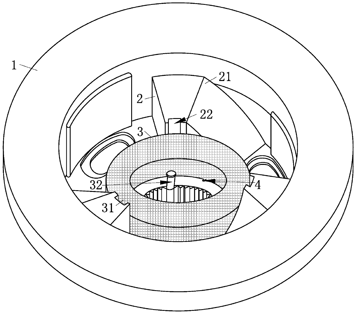
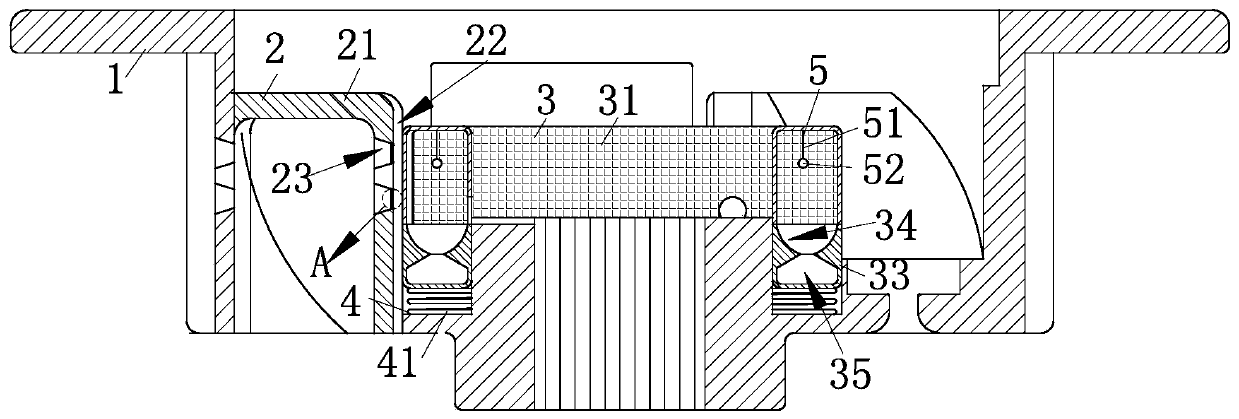
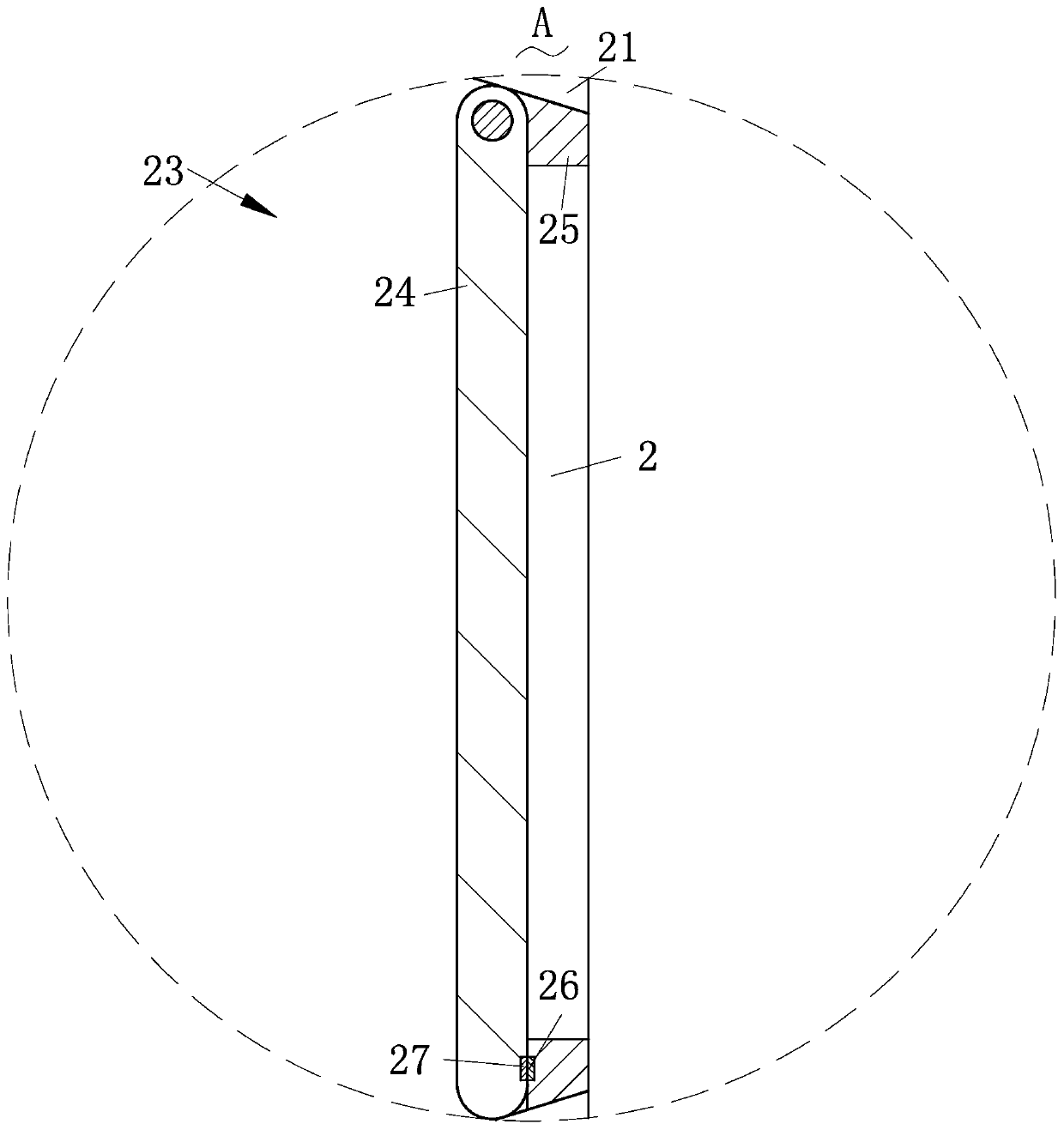
[0023] Such as Figure 1-Figure 5 As shown, a sliding clutch lubricating mechanism according to the present invention includes a center cover 1, a lubricating mechanism 2, a filter mechanism 3, a fixing mechanism 4 and an anti-blocking mechanism 5, and the center cover 1 used for socketing the main shaft is fixed and useful The lubricating mechanism 2 for lubricating the friction plate, the filtering mechanism 3 for filtering the impurities in the lubricating ...


PUM


Abstract

The invention discloses a sliding clutch lubricating mechanism. The lubricating mechanism comprises a center cover, the lubricating mechanism, a filtering mechanism, a fixing mechanism and an anti-blocking mechanism. The lubricating mechanism has advantages that the filtering mechanism is slidably connected to the center cover and the lubricating mechanism, impurities in lubricating oil are filtered and collected through the filtering mechanism, the impurities are prevented from blocking flow guide holes, and circulation of the lubricating oil is facilitated; the impurities in the lubricatingoil are prevented from making contact with a structure in a cam so that abrasion of the structure in the cam is not increased; the lubricating mechanism is fixed to the center cover, the lubricating mechanism is slidably connected with the filtering mechanism, and through using an oil guide groove and an oil guide hole arranged in the cam, the lubricating oil can conveniently enter into the cam ina semi-forced mode under an effect of a centrifugal force so as to lubricate the structure in the cam; and the anti-blocking mechanism is fixedly connected to the filtering mechanism, the filtering mechanism is knocked through the anti-blocking mechanism, the filtering mechanism is prevented from being blocked, and the lubricating oil can pass through conveniently.

Description

technical field [0001] The invention relates to a lubricating mechanism, in particular to a sliding clutch lubricating mechanism, which belongs to the technical field of clutches. Background technique [0002] The clutch is located in the flywheel housing between the engine and the gearbox, and the clutch assembly is fixed on the rear plane of the flywheel with screws, and the output shaft of the clutch is the input shaft of the gearbox. During the driving process of the car, the driver can step on or release the clutch pedal as needed to temporarily separate and gradually engage the engine and the transmission, so as to cut off or transmit the power input from the engine to the transmission. Clutches are common components in mechanical transmissions that can disengage or engage the transmission system at any time. The basic requirements are: smooth joint, rapid and thorough separation; convenient adjustment and repair; small external size; small mass; good wear resistance ...

Claims


Application Information

Patent Timeline
IPC IPC(8): F16H57/04
CPCF16H57/0404F16H57/0473
Inventor 陈俊智陈勇全陈宁张督玄吴芳振翁宝泉
Owner JINAN HONGZHENG TECH
Learn More