Novel camera lens assembly and projector

A lens assembly and a new type of technology, applied in the field of projectors, can solve the problems that the lens is difficult to replace quickly and cannot be well applied to new projectors.

Pending Publication Date: 2020-04-21
上海星迅科技有限公司
View PDF0 Cites 1 Cited by
  • Summary
  • Abstract
  • Description
  • Claims
  • Application Information

AI Technical Summary

Problems solved by technology

[0004] Aiming at the problems existing in the prior art that the lenses for projection lamps are difficult to replace quickly and cannot be well adapted to new projectors, the purpose of the present invention is to provide a new type of lens assembly

Method used


Image

  • Novel camera lens assembly and projector
  • Novel camera lens assembly and projector

Examples


Embodiment 1

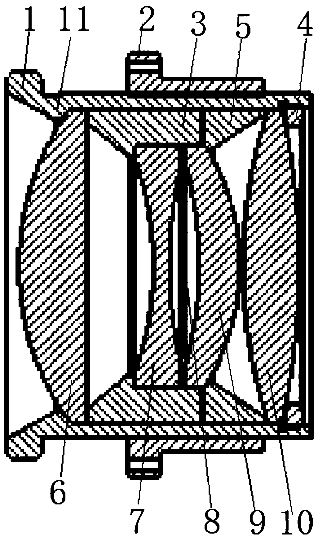
[0025] like figure 1 As shown, the present invention firstly provides a new type of lens assembly, including a lens cover 1 , an adjustment cover 2 , a lens cover 3 and a locking ring 4 . Wherein, the above-mentioned lens case 1 is in the shape of a cylinder, the lens case 3 and the locking ring 4 are sequentially arranged in the lens case 1 from front to back, and the outer wall of the lens case 3 is matched with the inner wall of the lens case 1 so that the lens case 3 It can move smoothly, and the outer wall of the locking ring 4 is threadedly connected with the inner wall of the lens case 1 .

[0026] The front end of the inner wall of the lens case 1 is provided with a limiting convex ring 11, which is integrally formed on the inner wall of the lens case 1, and the limiting convex ring 11 is used to prevent the lens from falling off from the front end of the lens case 1. The front end and / or the rear end of the inner wall of the lens case 3 are provided with lens steps f...

Embodiment 2

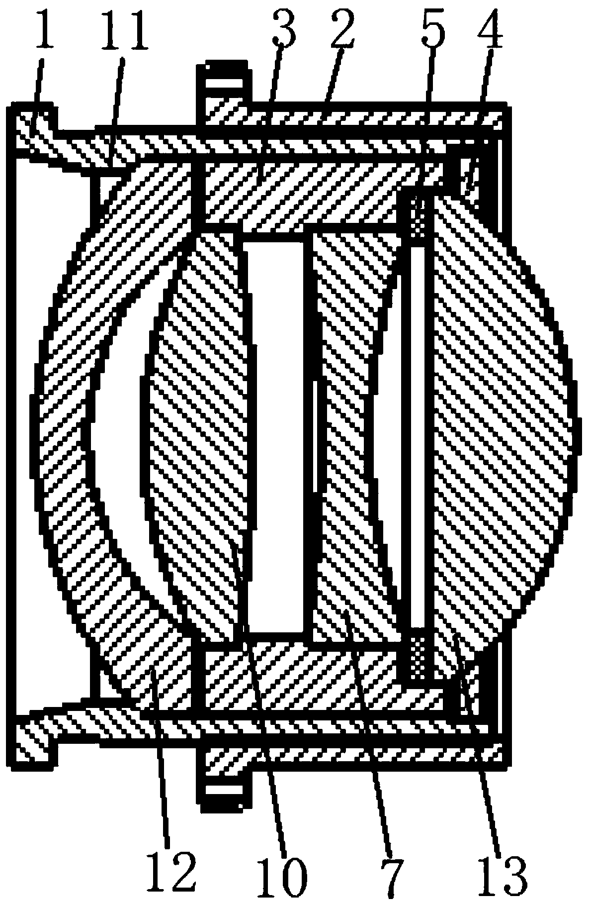
[0032] It differs from Embodiment 1 in that: as figure 2 As shown, in this embodiment, a convex-concave mirror 12 is pressed between the limiting convex ring 11 and the lens cover 3 , and the convex-concave mirror 12 refers to a lens with a convex front end and a concave rear end. And in the present embodiment, the front end and the rear end of the inner wall of the lens cover 3 all have the above-mentioned lens steps, and what is arranged on the lens steps at the front end of the inner wall of the lens cover 3 is a biconvex mirror 10, which is arranged behind the inner wall of the lens cover 3 It is double concave mirror 7 that is installed on the eyeglass step at the end. And what press-fit between the lens pressure ring 3 and the locking ring 4 is a plano-convex mirror 13 . Specifically in this embodiment, the rear end of the inner wall of the lens cover 3 is also provided with a lens pressure ring installation step, the diameter of the lens pressure ring installation ste...


PUM


Abstract

The invention discloses a novel camera lens assembly, which belongs to the field of projectors. The novel lens assembly comprises a camera lens sleeve, an adjusting sleeve, a lens sleeve, a locking ring and a lens pressing ring, wherein the lens sleeve and the locking ring are sequentially arranged in the camera lens sleeve from front to back, the outer wall of the lens sleeve is in clearance fitwith the inner wall of the camera lens sleeve, and the outer wall of the locking ring is in threaded connection with the inner wall of the camera lens sleeve; a limiting convex ring is arranged at thefront end of the inner wall of the camera lens sleeve; lens steps are arranged at the front end and/or the rear end of the inner wall of the lens sleeve; the lens pressing ring is pressed between thelens sleeve and the locking ring, and the inner wall of the lens pressing ring protrudes out of the inner wall of the lens step; and the inner wall of the adjusting sleeve is in threaded connection with the outer wall of the camera lens sleeve, the outer wall of the adjusting sleeve is provided with a connecting convex ring, and a connecting hole is formed in the connecting convex ring. The novelcamera lens assembly is simple in structure and reasonable in design, different types of camera lens assemblies can be implemented by rapidly replacing different lenses, and therefore the camera lensassembly is suitable for different occasions and projectors, and the position of the camera lens can be finely adjusted in the using process.

Description

technical field [0001] The invention relates to the field of projectors, in particular to a novel lens assembly and a projector. Background technique [0002] Projector lamp, also known as projector, is a device that can project images or videos onto the screen. When it is used for general lighting, it can be widely used in outdoor lighting projects in homes, offices, schools and entertainment venues. At the same time It can also be used to create various lighting effects and project the required patterns. [0003] A projector usually includes a frame, a power supply, a light source, a controller, a film winding mechanism, and a lens. At the same time, depending on projection requirements and usage occasions, it is usually necessary to replace different types of lenses for the projection lamp. However, in the prior art, it is inconvenient to install and fix the lens on the lamp holder of the projection lamp, and it takes a long time to replace the lens each time. Moreover,...

Claims


Application Information

Patent Timeline
Patent Type & Authority Applications(China)
IPC IPC(8): G02B7/02G03B21/14
CPCG02B7/021G03B21/14G03B21/142
Inventor 邓性星
Owner 上海星迅科技有限公司
Why Eureka
Try Eureka