A wearable fingertip force feedback device

A feedback device and finger cot technology, applied in the field of force feedback, can solve the problem of limited range of force feedback

Active Publication Date: 2021-04-16
NANJING UNIV OF AERONAUTICS & ASTRONAUTICS +1
View PDF11 Cites 0 Cited by
  • Summary
  • Abstract
  • Description
  • Claims
  • Application Information

AI Technical Summary

Problems solved by technology

Although some existing devices such as PhantomOmni, Omega, and Delta can realize force feedback, they mainly provide feedback force to the large limb joints of the human body and the range of force feedback is limited.

Method used


Image

  • A wearable fingertip force feedback device
  • A wearable fingertip force feedback device
  • A wearable fingertip force feedback device

Examples


Embodiment Construction

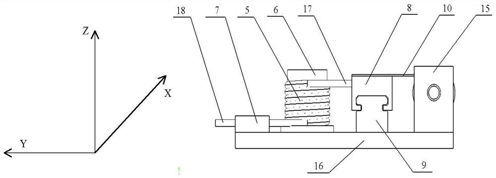
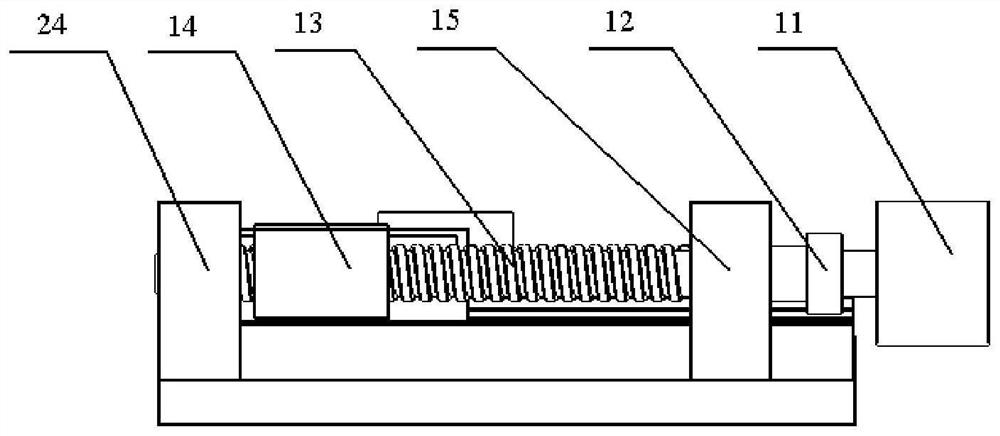
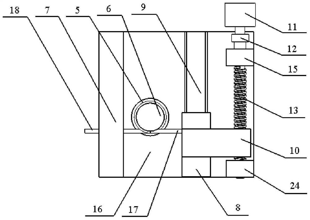
[0024] Such as Figure 1-15 As shown, a wearable fingertip force feedback device includes: Velcro 1, a first finger ring 19, a second finger ring 20, a finger cot 2, a string 4, a torsion spring 5, a torsion spring shaft 6, and a baffle 7 , slider 8, guide rail 9, transition plate 10, motor 11, coupling 12, lead screw 13, nut 14, first lead screw support 15, second lead screw support 24, base 16, the Velcro 1 Felt 3 is attached to the front and back of the front and back, and elastic bands are installed inside. The first finger ring 19, the second finger ring 20, and the finger cot 2 are successively installed on the proximal joint 21, middle joint 22, and distal joint 23 of the finger, and the first The finger ring 19, the second finger ring 20, and the finger ring 2 are all provided with a string 4 through holes, and one end of the string 4 links to each other with a torsion arm 18 of the torsion spring 5, and the other end passes through the first finger ring 19 and the sec...


PUM


Abstract

The invention discloses a wearable fingertip force feedback device, comprising: Velcro, finger cots, strings, torsion springs, torsion spring shafts, sliders, guide rails, transition plates, motors, couplings, lead screws, Nut, first lead screw bracket, base, first finger ring, second finger ring and second lead screw bracket. The invention can output the feedback force to the fingertips of the human body to enhance the force-tactile perception in the human-computer interaction.

Description

technical field [0001] The invention relates to the technical field of force feedback, in particular to a wearable fingertip force feedback device. Background technique [0002] Today, technologies such as somatosensory, multi-touch, virtual reality, and remote operation have gradually penetrated into various fields such as medical care, education, and games as several ways of human-computer interaction. Taking virtual reality as an example, although it has matured in terms of vision and hearing, it still has insufficient haptic perception, that is, it lacks a control mechanism that can realize force feedback and integrate with virtual reality technology to enhance the technology. The sense of immersion and reality brought by users. Although some existing devices such as PhantomOmni, Omega, and Delta can realize force feedback, they mainly provide feedback force to large limb joints of the human body and the range of action of force feedback is limited. Therefore, developi...

Claims


Application Information

Patent Timeline
Patent Type & Authority Patents(China)
IPC IPC(8): G06F3/01
CPCG06F3/014G06F3/016
Inventor 吴常铖宋天赐曹青青费飞杨德华朱永凯陆熊严余超
Owner NANJING UNIV OF AERONAUTICS & ASTRONAUTICS
Why Eureka
Try Eureka