Street lamp cable efficient traction device

A traction device and cable technology, which is applied in the directions of cable installation device, cable installation, cable laying equipment, etc., can solve the problems of cable traction that cannot be applied to various specifications, inconvenient to move and handle, and limited in scope of application. Handling, wide application range, stable and reliable traction

Inactive Publication Date: 2020-04-21
赣州雄安照明科技有限公司
View PDF3 Cites 4 Cited by
  • Summary
  • Abstract
  • Description
  • Claims
  • Application Information

AI Technical Summary

Problems solved by technology

[0003] Most of the current street lamp cable pulling devices are bulky and inconvenient to move and carry; moreover, they cannot be applied to pulling cables of various specifications, and the scope of application is limited

Method used


Image

  • Street lamp cable efficient traction device
  • Street lamp cable efficient traction device
  • Street lamp cable efficient traction device

Examples


Embodiment 1

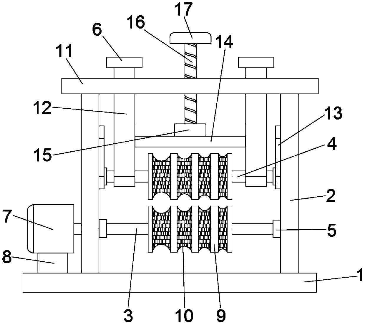
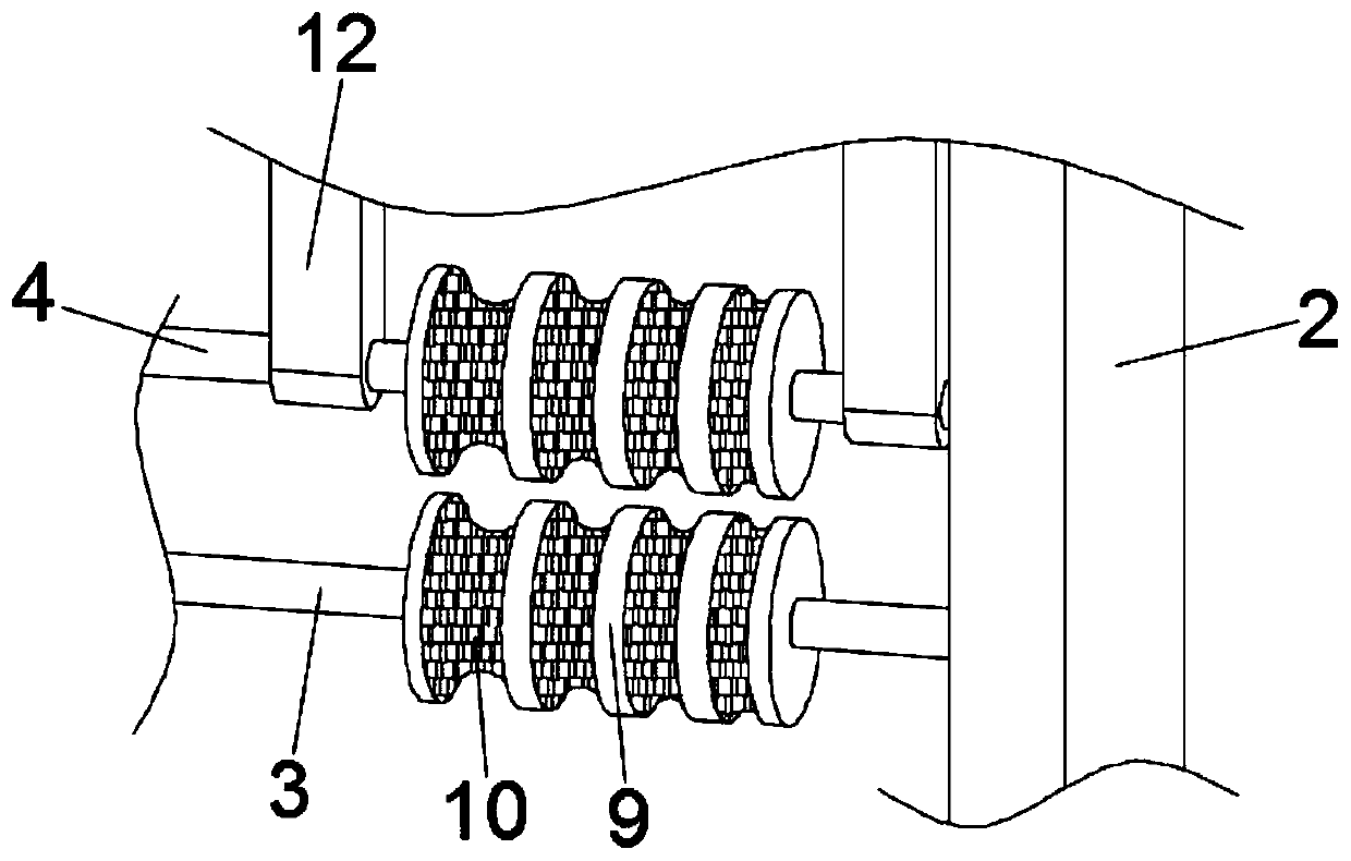
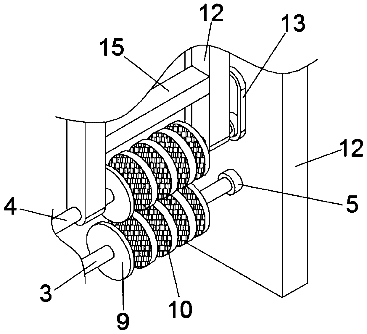
[0024] see figure 1 , a high-efficiency traction device for street lamp cables, including a base 1, support plates 2 are vertically fixed on both sides of the upper end surface of the base 1, and multiple sets of traction components are horizontally arranged between the support plates 2 on both sides, and the traction components include active shaft 3 and driven shaft 4, both ends of the driving shaft 3 and the driven shaft 4 are rotatably mounted on the support plate 2 through the bearing housing 5, and the driving shaft 3 and the driven shaft 4 are fixed with matching traction Wheel 9, the traction wheel 9 is provided with a plurality of grooves 10 with different opening widths and depths, one end of the drive shaft 3 is connected with a traction motor 7, and the traction motor 7 is fixed on the base 1 through a motor base 8; The top of the support plate 2 is fixed with a top plate 11, and the top plate 11 is provided with a lifting mechanism that drives the driven shaft 4 t...

Embodiment 2

[0035] Due to the heavy weight of the cable itself, it is inevitable that it will slide relative to the inner wall of the groove 10 during the traction process, resulting in traction failure. Therefore, this embodiment has made further improvements on the basis of embodiment 1. The improvements are as follows: : the groove 10 is provided with an anti-slip layer, through which the anti-slip layer is in contact with the cable, thereby greatly increasing the friction coefficient between the cable and the anti-slip layer, which can effectively prevent the cable from slipping during traction;

[0036] The specific material of the anti-slip layer is not limited, but while ensuring a large friction coefficient, it also needs to have better wear resistance, because after a long period of traction, the cable will wear the surface of the anti-slip layer. , Preferably, the anti-slip layer is made of wear-resistant rubber.

[0037] The high-efficiency traction device for street lamp cable...


PUM


Abstract

The invention discloses a street lamp cable efficient traction device comprising a base. Supporting plates are vertically fixed to the two sides of the upper end face of the base. A plurality of traction assemblies are horizontally arranged between the supporting plates on the two sides, each traction assembly comprises a driving shaft and a driven shaft, the two ends of each driving shaft and thetwo ends of each driven shaft are rotationally installed on the supporting plates through bearing pedestals, traction wheels matched with each other are fixed to the driving shafts and the driven shafts, and a plurality of grooves are formed in the traction wheels; a top plate is fixed to the top of the supporting plate and provided with a lifting mechanism for driving the driven shaft to move upward and downward. According to the street lamp cable efficient traction device, traction force is dispersed through multiple traction assemblies, and traction is more stable and reliable; a pluralityof grooves with different opening widths and depths are formed in the traction wheels so that the cable traction device is suitable for traction of cables of different specifications, wide in application range, convenient and rapid to operate and high in traction efficiency.

Description

technical field [0001] The invention relates to the technical field of electric power construction, in particular to a high-efficiency traction device for street lamp cables. Background technique [0002] During the construction of street lamps, it is necessary to bury street lamp cables along the way. In order to facilitate transportation, street lamp cables are generally collected and stored on reels. can be used directly. [0003] Most of the current street lamp cable pulling devices are bulky and inconvenient to move and carry; moreover, they cannot be applied to pulling cables of various specifications, and the scope of application is limited. Contents of the invention [0004] The object of the present invention is to provide a high-efficiency traction device for street lamp cables to solve the problems raised in the above-mentioned background technology. [0005] To achieve the above object, the present invention provides the following technical solutions: [000...

Claims


Application Information

Patent Timeline
Patent Type & Authority Applications(China)
IPC IPC(8): H02G1/08
CPCH02G1/081
Inventor 邱琴英
Owner 赣州雄安照明科技有限公司
Why Eureka
Try Eureka