
Reflection type spatial coding high-resolution light field imaging device and method
A technology of spatial coding and light field imaging, which is applied in the directions of image communication, TV, color TV components, etc., can solve the problems of high cost and achieve the effects of avoiding design constraints, strong adaptability and cost saving
- Summary
- Abstract
- Description
- Claims
- Application Information
AI Technical Summary
Problems solved by technology
Method used
Image

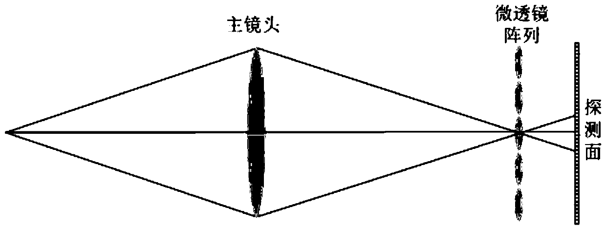
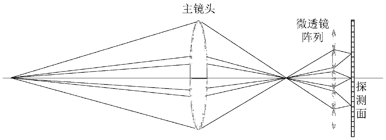
Examples
Embodiment Construction
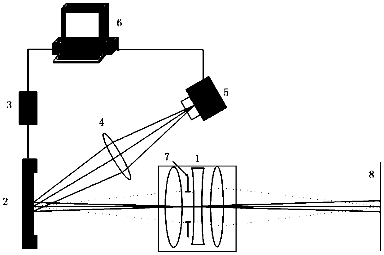
[0038] Such as image 3 As shown, the reflective spatially encoded high-resolution light field imaging device consists of an imaging objective lens 1, a digital micromirror array 2 (hereinafter referred to as DMD), a digital micromirror array controller 3 (hereinafter referred to as DMD controller), and an aperture imaging lens 4 , a two-dimensional array detector 5 and a computer 6.
[0039] Among them, the imaging objective lens 1 is provided with an aperture stop 7; DMD2 is conjugate to the object plane, the detection surface of the two-dimensional array detector 2 is conjugate to the aperture stop 7, and each point on the two-dimensional array detector 2 is conjugate to the aperture stop 7. Each point on 7 corresponds one by one;
[0040] Computer 6 sends flipping information to DMD controller 3; Turning information is the order information of each micromirror flipping in DMD2; The sequence information of each micromirror flipping in the present embodiment is represented ...
PUM
 Abstract
Description
Claims
Application Information