Tube plate lead-out type condensate water outlet structure

A technology of outlet structure and condensed water, which is applied in the field of chemical machinery, can solve the problems of poor welding position, high cost, and residue, and achieve the effects of avoiding heat treatment, improving structural strength, and reducing production costs

Pending Publication Date: 2020-04-24
ZHANGHUAJI SUZHOU HEAVY EQUIP CO LTD
View PDF0 Cites 0 Cited by
  • Summary
  • Abstract
  • Description
  • Claims
  • Application Information

AI Technical Summary

Problems solved by technology

The disadvantages of this structure are: 1. The condensed water is not drained cleanly and there are residues; 2. Holes need to be opened on the cylinder of the heating chamber, thereby reducing the structural strength of the cylinder of the heating chamber; 3. The gap between the condensate pipe and the cylinder of the heating chamber The gap is fillet welding, the welding position is not good, and the penetration cannot be achieved. On-site welding and on-site heat treatment are required. The heat treatment is not thorough, which is unfavorable to the alkali corrosion of the equipment, and the cost of on-site welding and on-site heat treatment is relatively high.

Method used


Image

  • Tube plate lead-out type condensate water outlet structure
  • Tube plate lead-out type condensate water outlet structure
  • Tube plate lead-out type condensate water outlet structure

Examples


Embodiment Construction

[0017] In the following, the structure of a tube-sheet drawn-out condensed water outlet according to the present invention will be further described in detail through specific embodiments.

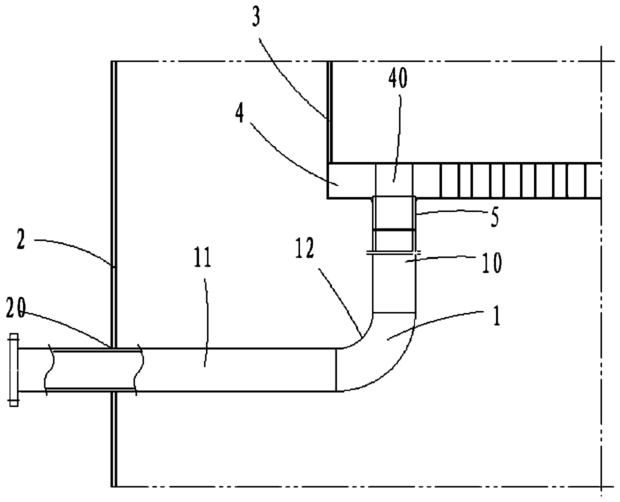
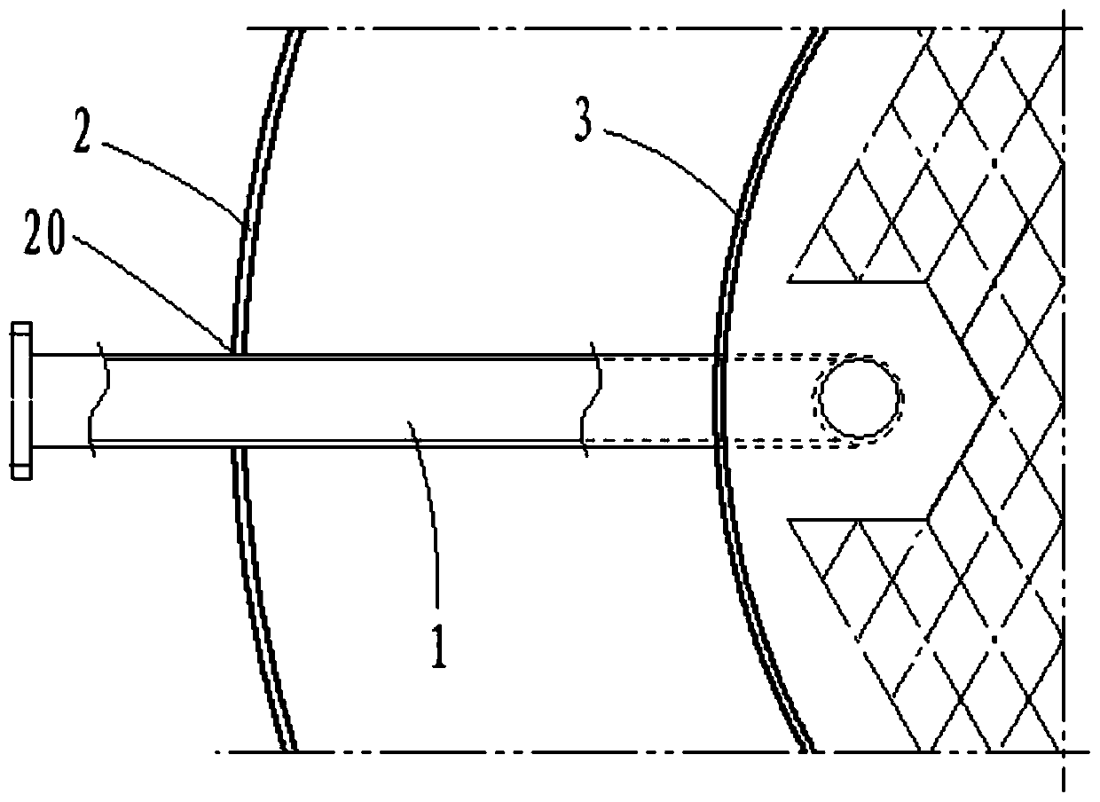
[0018] ginseng figure 2 and image 3 As shown, a tube plate lead-out condensed water outlet structure, including: condensed water pipe 1, separation chamber cylinder 2, heating chamber cylinder 3 and lower tube plate 4, the separation chamber cylinder 2 is located on the heating chamber cylinder 3 outside.

[0019] The cylinder body 2 of the separation chamber is provided with a first opening 20, the lower tube plate 4 is provided with a second opening 40, and a lead-out pipe 5 is welded below the second opening 40, and the lead-out pipe Fillet welding is between the upper end of 5 and the bottom surface of lower tube plate 4 .

[0020] The condensed water pipe 1 includes a first straight pipe section 10, a second straight pipe section 11 and an elbow section 12 welded to each other. T...


PUM


Abstract

The invention relates to a tube plate lead-out type condensate water outlet structure. The tube plate lead-out type condensate water outlet structure comprises a condensate water tube, a separation chamber barrel, a heating chamber barrel and a lower tube plate, the separation chamber barrel is positioned on the outer side of the heating chamber barrel, a first opening is formed in the separationchamber barrel, a second opening is formed in the lower tube plate, a lead-out tube is welded to the lower portion of the second opening, one end of the condensate water tube is welded to the lead-outtube, the other end of the condensate water tube penetrates through the first opening of the separation chamber barrel and then protrudes out of the separation chamber barrel, and the condensate water tube is welded to the first opening, so the structural strength of the heating chamber barrel is greatly improved.

Description

【Technical field】 [0001] The invention relates to the field of chemical machinery, in particular to a tube plate-leading condensed water outlet structure. 【Background technique】 [0002] The working principle of the tubular falling film evaporator is as follows: the mother liquor enters the distributor from the upper cover of the heating chamber, and evenly enters the heat exchange tube after distribution and film distribution, and descends along the tube wall of the heat exchange tube, and the steam in the shell side of the heating chamber After the heat exchange, it will pour directly into the separation chamber. When the solution falls into the separation chamber, the foam layer on the liquid surface of the separation chamber will be crushed at the same time. The solution will self-evaporate in the separation chamber. The shell side of the next effect heating chamber is heated. [0003] The steam in the shell side of the heating chamber undergoes a phase change after hea...

Claims


Application Information

Patent Timeline
Patent Type & Authority Applications(China)
IPC IPC(8): B01D5/00
CPCB01D5/006B01D5/009
Inventor 狐素琴
Owner ZHANGHUAJI SUZHOU HEAVY EQUIP CO LTD
Why Eureka
Try Eureka