Steel pipe welding device and working method

A welding device and technology for steel pipes, applied in the field of steel pipe welding

Active Publication Date: 2020-04-24
新疆神州通新材料股份有限公司
View PDF5 Cites 9 Cited by
  • Summary
  • Abstract
  • Description
  • Claims
  • Application Information

AI Technical Summary

Problems solved by technology

[0003] The purpose of the present invention is to provide a steel pipe welding device and its working method, which is used to solve the technical problem of welding steel pipes with different diameters

Method used


Image

  • Steel pipe welding device and working method
  • Steel pipe welding device and working method
  • Steel pipe welding device and working method

Examples


Embodiment Construction

[0029] In order to clearly illustrate the technical features of the present solution, the present invention will be described in detail below through specific implementation methods and in conjunction with the accompanying drawings. It should be noted that components illustrated in the figures are not necessarily drawn to scale. Descriptions of well-known components and techniques are omitted herein to avoid unnecessarily limiting the present invention.

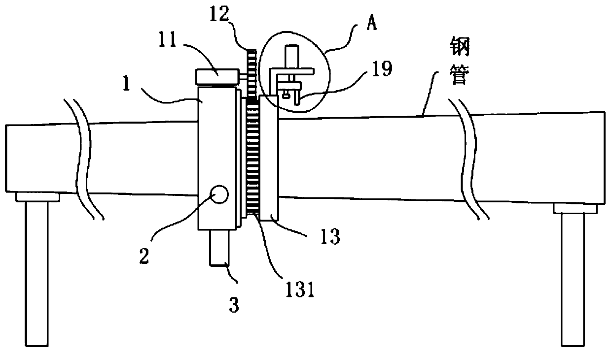
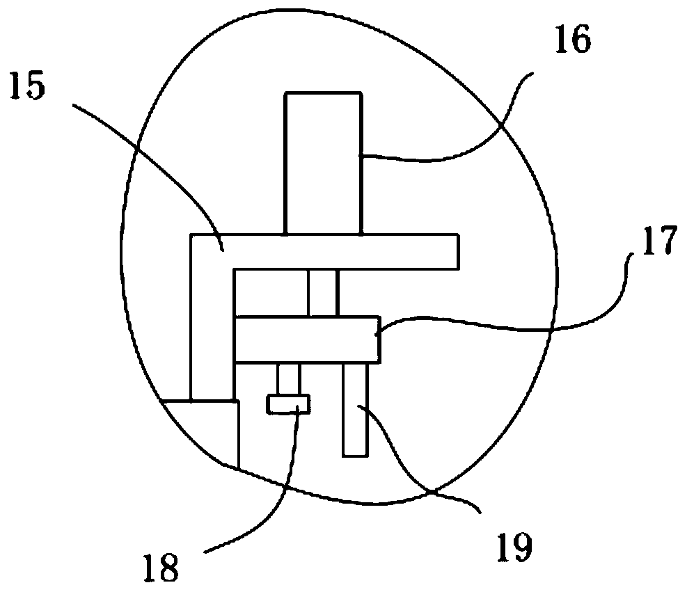
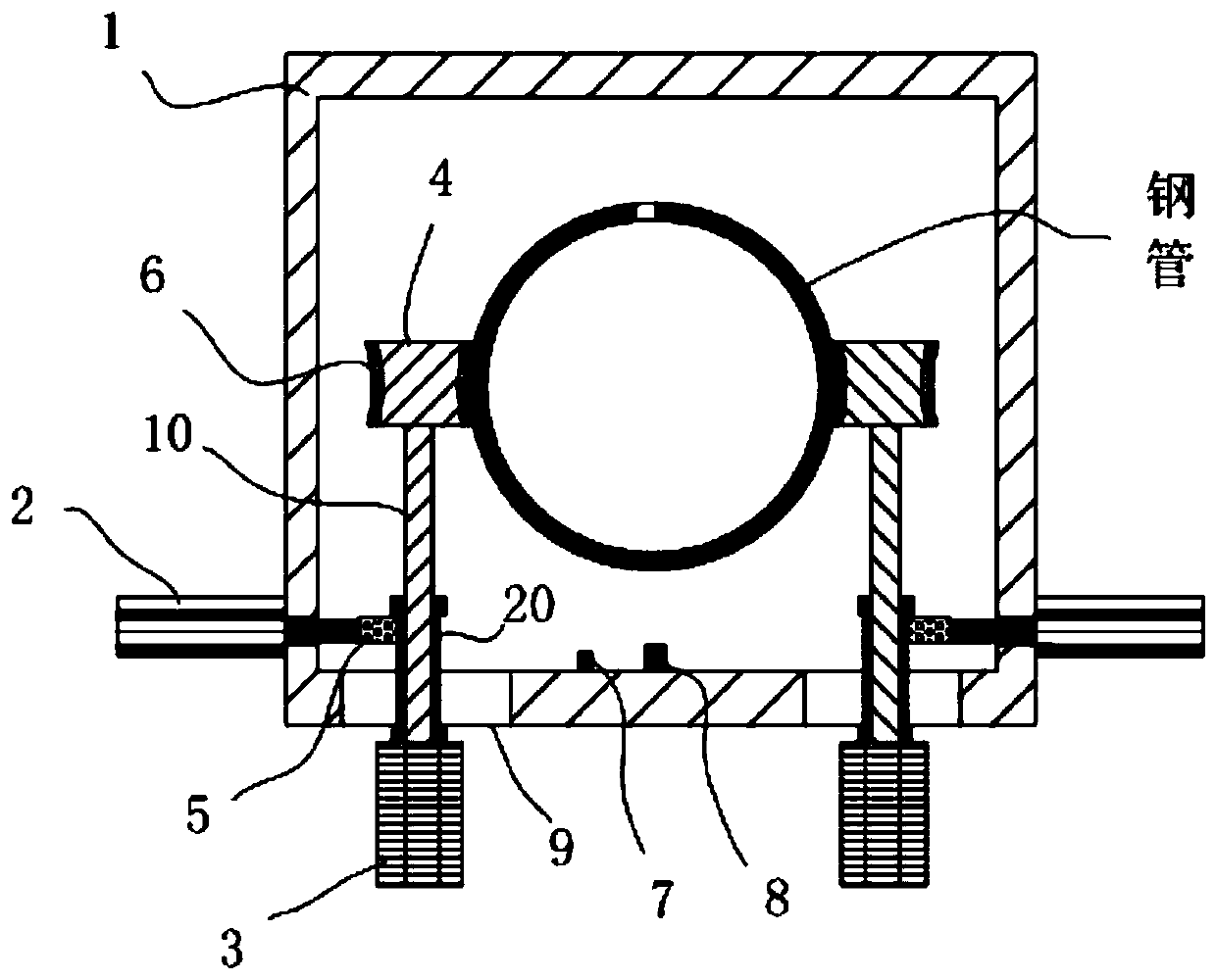
[0030] like Figures 1 to 4 As shown, a steel pipe welding device includes a control system, and a clamping traveling mechanism, a rotating mechanism and a welding mechanism electrically connected to the control system. The clamping traveling mechanism is used to drive the device to travel longitudinally on the steel pipe, and the welding mechanism is used to The longitudinal seam on the steel pipe and the annular seam at the butt joint port of the steel pipe are welded, and the rotating mechanism is installed on the clampin...


PUM


Abstract

The invention aims to provide a steel pipe welding device and a working method thereof to solve the technical problem of welding steel pipes with different diameters. The steel pipe welding device comprises a control system, a clamping walking mechanism, a rotating mechanism and a welding mechanism, wherein the clamping walking mechanism, the rotating mechanism and the welding mechanism are electrically connected with the control system; the clamping walking mechanism is used for driving the device to longitudinally walk on a steel pipe; the welding mechanism is used for welding longitudinal welding seams on the steel pipe and annular welding seams at butt joint ports of the steel pipe; and the rotating mechanism is installed on the clamping walking mechanism and used for driving the welding mechanism to rotate.

Description

technical field [0001] The invention relates to the technical field of steel pipe welding, in particular to a steel pipe welding device and a working method thereof. Background technique [0002] Steel pipes are widely used in all walks of life. We usually see steel pipes with equal diameters, and steel pipes with unequal diameters exist in some special fields. Some unequal-diameter steel pipes are rolled by steel plates, and the seams are welded after the steel pipes are rolled into shape. For applications with special requirements for length, multiple sections of unequal diameter steel pipes need to be welded to lengthen. In the prior art, manual welding is usually used, and the welding efficiency of this method is relatively low. Contents of the invention [0003] The object of the present invention is to provide a steel pipe welding device and its working method, which are used to solve the technical problem of welding steel pipes with different diameters. [0004] ...

Claims


Application Information

Patent Timeline
Patent Type & Authority Applications(China)
IPC IPC(8): B23K37/053B23K37/02B23K37/00B23K101/06B23K103/04
CPCB23K37/00B23K37/02B23K37/053B23K2101/06B23K2103/04
Inventor 韩玉铭
Owner 新疆神州通新材料股份有限公司
Why Eureka
Try Eureka