
Rod unloader for down-the-hole drilling rig

A down-the-hole drilling rig and rod unloading technology, which is applied in the direction of drill pipes, drill pipes, drilling equipment, etc., can solve the problems of large wear of claws and drill pipes, difficulty in unloading rods, uneven clamping force, etc., and achieve uniform force , to ensure the effect of motion synchronization

Active Publication Date: 2021-02-26
NANTONG YONGDA PIPE IND
View PDF7 Cites 0 Cited by
  • Summary
  • Abstract
  • Description
  • Claims
  • Application Information

AI Technical Summary

Problems solved by technology

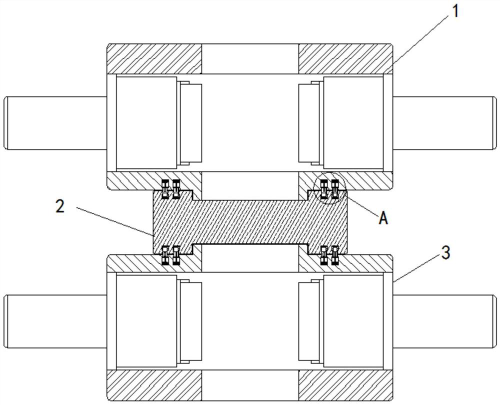
[0005] Aiming at the deficiencies of the prior art, the present invention provides a rod unloader for a down-the-hole drilling rig, which has the advantages of uniform clamping force when unloading the rod, reduces loss, can effectively ensure that the upper and lower clamping devices are concentric, and is convenient for unloading the rod, etc., which solves the problem of general The rod unloader of the down-the-hole drilling rig has uneven clamping force when unloading the rod, resulting in greater wear and tear on the claws and the drill pipe, and the unevenness of the upper and lower clamping devices, resulting in difficulty in unloading the rod

Method used


Image

  • Rod unloader for down-the-hole drilling rig
  • Rod unloader for down-the-hole drilling rig
  • Rod unloader for down-the-hole drilling rig

Examples


Embodiment Construction

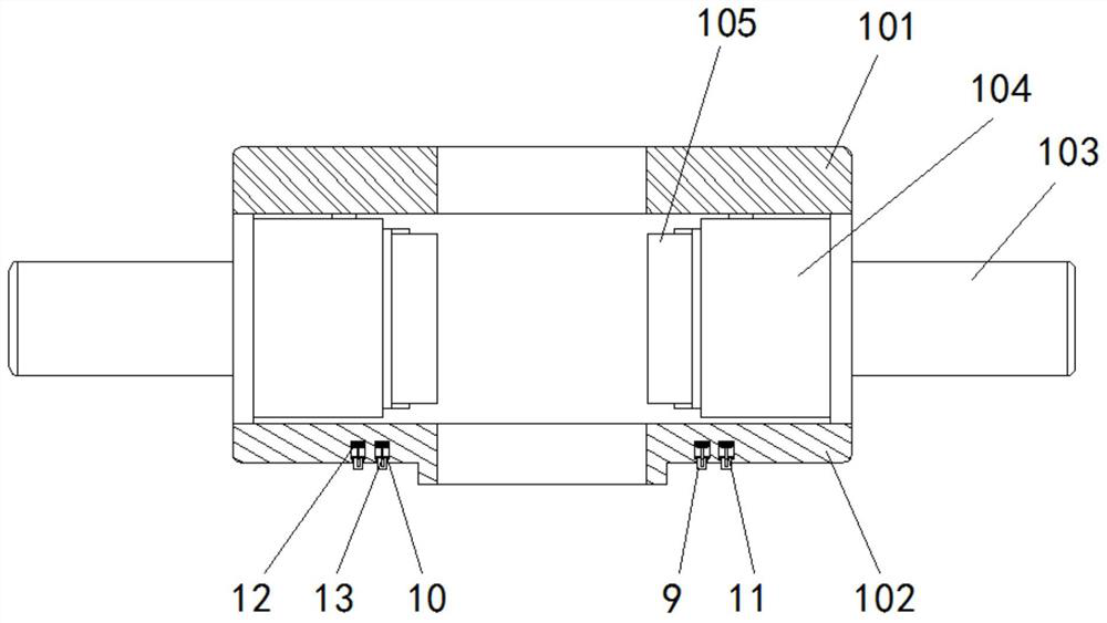
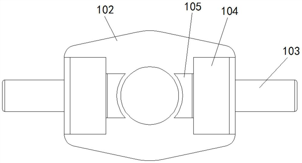
[0028] The following will clearly and completely describe the technical solutions in the embodiments of the present invention with reference to the accompanying drawings in the embodiments of the present invention. Obviously, the described embodiments are only some, not all, embodiments of the present invention. Based on the embodiments of the present invention, all other embodiments obtained by persons of ordinary skill in the art without making creative efforts belong to the protection scope of the present invention.

[0029] see Figure 1-8 , a rod unloader for a down-the-hole drilling rig, comprising an upper clamping device 1, a sleeve 2, a lower clamping device 3, a center cover 101, a positioning cover 102, a clamping cylinder 103, a push plate 104, claws 105, Protrusion 4, groove 1 5, spring 6, retaining ring 7, pressure sensor 8, pressure block 9, groove 2 10, magnetic sheet 11, electromagnet 12, guide rod 13, cylinder 14, slide seat 15, sliding Column one 16, slidin...


PUM


Abstract

The invention relates to the technical field of drilling rig equipment, and discloses a rod unloader for a down-the-hole drilling rig, which includes an upper clamping device, a sleeve, a lower clamping device, a bump and a pressure block, and the top and bottom of the sleeve are movable There are protrusions distributed symmetrically on the left and right, and a pressure block corresponding to the protrusion is movably inserted on the side of the positioning cover close to the sleeve, and a magnetic piece is fixedly connected to the end of the pressure block away from the protrusion. The groove bottom of the groove two is fixedly connected with an electromagnet. For the down-the-hole drill rod unloader, after the electromagnet is energized, the pressing block squeezes the bump to make the retaining ring contact the pressure sensor. Through the signal light in the control center, you can know the alignment of groove 1 and groove 2, and the position of the clamping device. Adjust until it is aligned with the sleeve to ensure the concentricity of the three, and the jaws move synchronously through the connecting rod structure, the upper and lower clamping devices are concentric, and the force on both sides of the drill pipe is even, which effectively solves the problem when unloading the rod. The problem that the upper and lower clamping devices are not concentric.

Description

technical field [0001] The invention relates to the technical field of drilling rig equipment, in particular to a rod unloader for a down-the-hole drilling rig. Background technique [0002] The drill pipe of the down-the-hole drilling rig is usually relatively long, and generally consists of multiple short drill pipes threaded to form a long drill pipe. With the development of industrial technology, the unloading of the drill pipe has been mechanized. The rod unloader is mainly composed of an upper clamping device, an upper clamping cylinder, a lower clamping device and a lower clamping cylinder. The process of dismantling a drill pipe for a down-the-hole drilling rig is as follows: first, the upper clamping cylinder pushes the upper The clamping device clamps the upper drill pipe, and the lower clamping cylinder pushes the lower clamping device to clamp the lower drill pipe; secondly, the rod unloading hydraulic cylinder and the slewing mechanism start to work, so that the...

Claims


Application Information

Patent Timeline
Patent Type & Authority Patents(China)
IPC IPC(8): E21B19/16E21B19/10
CPCE21B19/10E21B19/161E21B19/165
Inventor 梁育娟
Owner NANTONG YONGDA PIPE IND
Learn More