Fingerprint identification terminal equipment

A fingerprint identification and terminal equipment technology, applied in the field of communication, can solve problems such as easily generating Newton rings and affecting the accurate collection of infrared light signals

Pending Publication Date: 2020-04-24
SHENZHEN LONGLI TECH CO LTD
View PDF5 Cites 0 Cited by
  • Summary
  • Abstract
  • Description
  • Claims
  • Application Information

AI Technical Summary

Problems solved by technology

like Figure 2-3 As shown, when the infrared light passes through the light guide plate 12 and the reflector 11 of the backlight module 120, Newton's rings are easily generated, which affects the accurate collection of infrared light signals.

Method used


Image

  • Fingerprint identification terminal equipment
  • Fingerprint identification terminal equipment
  • Fingerprint identification terminal equipment

Examples


Embodiment 1

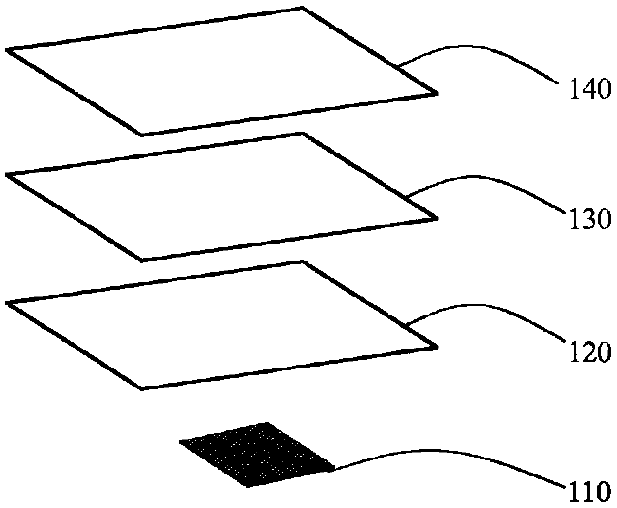
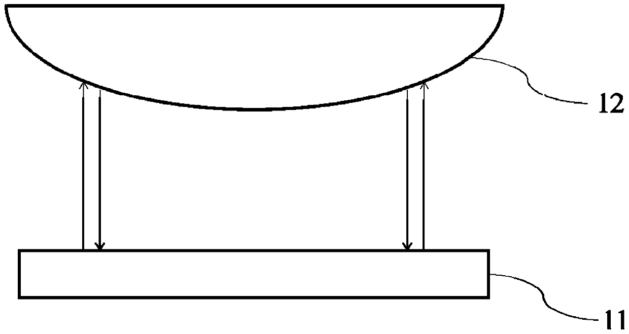
[0031] First, through figure 1 and Figure 4 According to Embodiment 1 of the present invention, a fingerprint recognition terminal device for fingerprint recognition in an LCD screen includes a glass cover plate 140, an LCD liquid crystal panel 130, a backlight module 120 and Fingerprint recognition sensor 110. The backlight module includes a light source 10, a light guide plate 12 arranged on one side of the light source 10, a reflective sheet 11 arranged below the light guide plate 13, and a reflective sheet 11 arranged between the light guide plate 13 and the reflective sheet 11. The light-transmitting sheet 12 is provided with a light-transmitting structure on the light-transmitting sheet 12. The size of the transparent sheet 12 corresponds to that of the light guide plate 13 . In order to avoid the influence of Newton's rings generated between the light guide plate 13 and the reflection sheet 11 on the fingerprint identification signal, the thickness of the light-tran...

Embodiment 2

[0035] Please refer to Figure 5 , is an exploded view of the backlight module of the fingerprint identification terminal device according to Embodiment 2 of the present invention. Only the differences between Embodiment 2 and Embodiment 1 will be described below, and the similarities will not be repeated here.

[0036] The size of the transparent sheet 12 corresponds to the fingerprint recognition area of ​​the fingerprint recognition terminal device.

Embodiment 3

[0038] Please refer to Figure 6 , is an exploded view of the backlight module of the fingerprint identification terminal device according to Embodiment 3 of the present invention. In the following, only the differences between Embodiment 3 and Embodiment 1 will be described, and the similarities will not be repeated here.

[0039] The fingerprint identification terminal device is not provided with a transparent sheet, but a transparent structure 12 is provided between the light guide plate 13 and the reflective sheet 11 . The transparent structure 12 is disposed on the reflective surface of the reflective sheet 11 . The light-transmitting structures 12 are radially distributed, and the density of the light-transmitting structures 12 near the fingerprint recognition area is higher than the density of the light-transmitting structures 12 in the far fingerprint recognition area. The transparent structure 12 is a circular prism.

[0040] The thickness of the light-transmitting...


PUM

PropertyMeasurementUnit
Thicknessaaaaaaaaaa

Abstract

The invention discloses fingerprint identification terminal equipment. The fingerprint identification terminal equipment comprises a glass cover plate, an LCD liquid crystal panel, a backlight moduleand a fingerprint identification sensor which are sequentially laminated from top to bottom, wherein the backlight module comprises a light source, a light guide plate, a reflector plate arranged below the light guide plate and a light-transmitting structure arranged between the light guide plate and the reflector plate, and the thickness of the light-transmitting structure is not smaller than 5 micrometers. The invention provides fingerprint identification terminal equipment for identifying fingerprints in an LCD (liquid crystal display) screen, which avoids the generation of Newton rings ofinfrared light signals, so that the infrared light fingerprint identification signals can effectively penetrate through the fingerprint identification terminal equipment and can be accurately collected.

Description

technical field [0001] The invention relates to the field of communication technology, in particular to a fingerprint recognition terminal device used for fingerprint recognition in an LCD screen. Background technique [0002] Fingerprint sensing and matching is a reliable and widely used technology. A common method of fingerprint identification involves scanning a sample fingerprint or an image thereof and storing the image and / or unique characteristics of the fingerprint image, the characteristics of the sample fingerprint can be compared with information from reference fingerprints already present in a database to determine the correct identification of the user , for example for verification purposes. In particular, in-display fingerprint recognition is currently becoming more and more popular due to its ease of operation and versatility, and its suitability for compact portable electronic devices. [0003] The fingerprint recognition display device in the LCD screen o...

Claims


Application Information

Patent Timeline
IPC IPC(8): G06K9/00G06K9/20
CPCG06V40/1324G06V10/147
Inventor 张小齐程述武彭益庄世强
Owner SHENZHEN LONGLI TECH CO LTD
Why Eureka
Try Eureka