
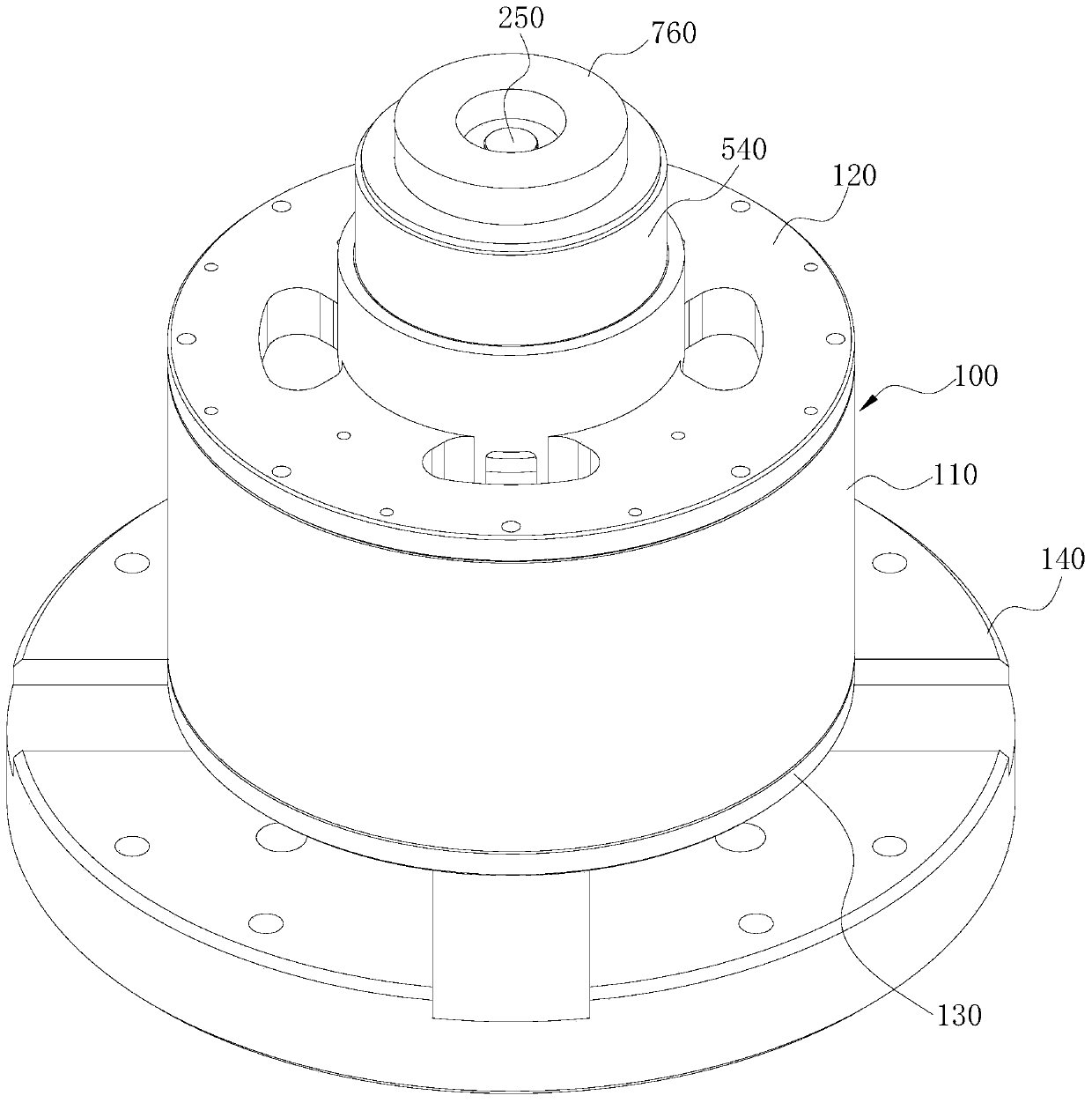
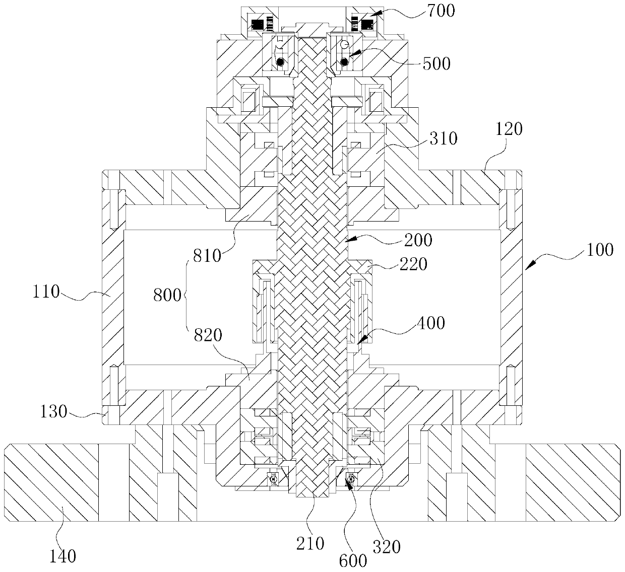
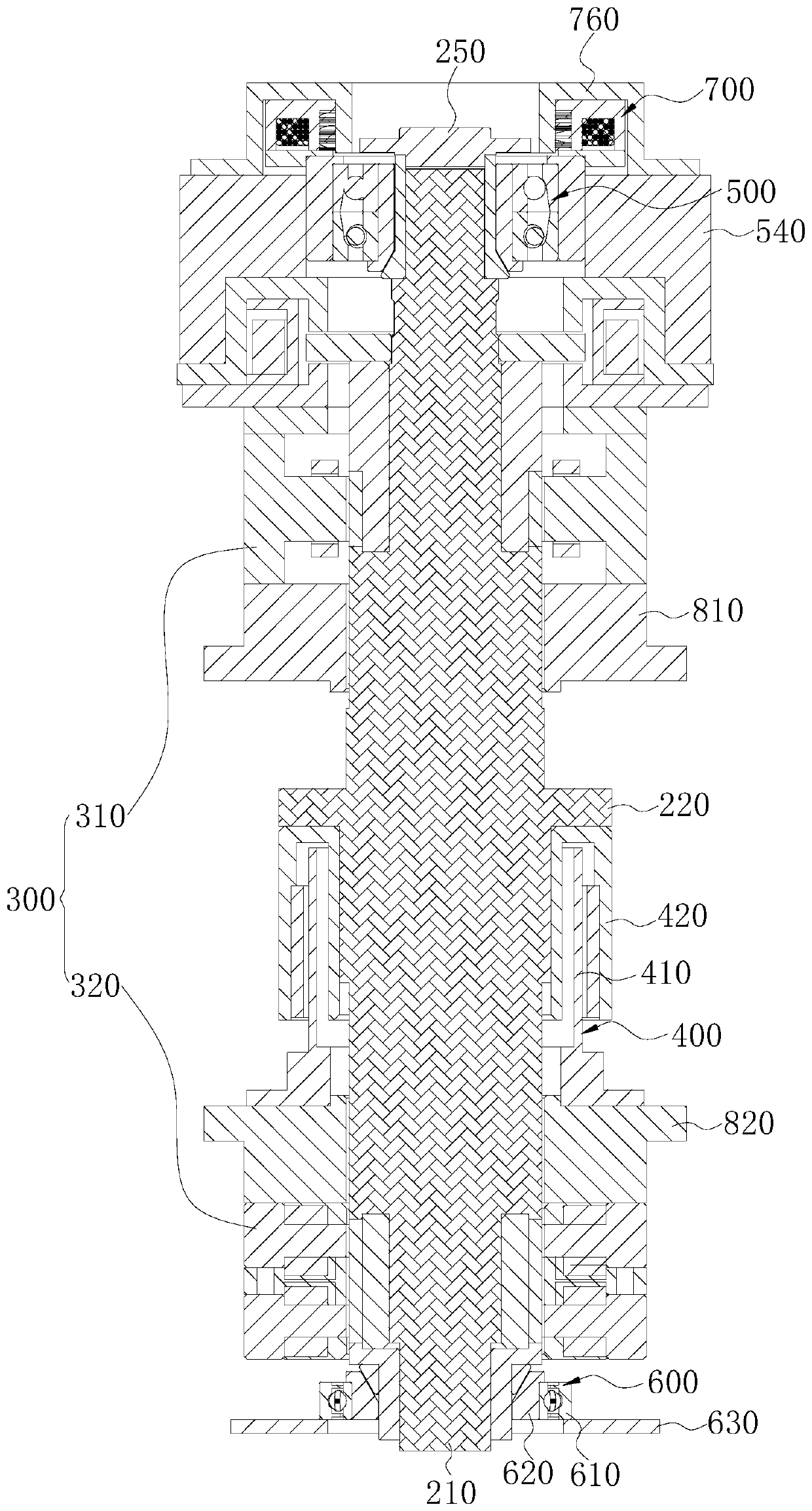
Magnetic suspension flywheel energy storage device

A flywheel energy storage and magnetic levitation technology, used in electromechanical devices, control mechanical energy, electrical components, etc., can solve the problems of rotor damage and fracture, uneven distribution, shorten the life of protected bearings, etc., to reduce collision damage and improve life.

Pending Publication Date: 2020-04-24
坎德拉(深圳)新能源科技有限公司
View PDF0 Cites 7 Cited by
  • Summary
  • Abstract
  • Description
  • Claims
  • Application Information

AI Technical Summary

Problems solved by technology

[0005] The purpose of this application is to provide a magnetic levitation flywheel energy storage device, which aims to solve the problem that in the prior art, when the flywheel fails or fails, the unevenly distributed rotational torque will shorten the life of the protective bearing and cause the rotor to be damaged and broken. question

Method used


Image

  • Magnetic suspension flywheel energy storage device
  • Magnetic suspension flywheel energy storage device
  • Magnetic suspension flywheel energy storage device

Examples


Embodiment Construction

[0034] Embodiments of the present application are described in detail below, examples of which are shown in the drawings, wherein the same or similar reference numerals denote the same or similar elements or elements having the same or similar functions throughout. The embodiments described below by referring to the figures are exemplary, and are intended to explain the present application, and should not be construed as limiting the present application.

[0035] In the description of the present application, it should be understood that the terms "length", "width", "upper", "lower", "front", "rear", "left", "right", "vertical", The orientation or positional relationship indicated by "horizontal", "top", "bottom", "inner", "outer", etc. are based on the orientation or positional relationship shown in the drawings, and are only for the convenience of describing the application and simplifying the description, rather than Nothing to indicate or imply that a referenced device or el...


PUM


Abstract

The invention belongs to the technical field of magnetic levitation energy storage equipment, and particularly relates to a magnetic levitation flywheel energy storage device. The magnetic levitationflywheel energy storage device comprises a shell, a flywheel rotor, a magnetic bearing and a stator and a rotor of a motor, an upper protection assembly, a lower protection assembly, and a driver. Theupper protection assembly comprises an upper protection bearing and an upper conical part, and the inner surface of the upper conical part is provided with a cylindrical surface and a conical surface. The lower protection assembly comprises a lower protection bearing and a lower conical part, and the inner surface of the lower conical part is provided with a cylindrical surface and a conical surface. The driver is electrically connected with a power supply structure of the magnetic suspension flywheel energy storage device. When power is off or the flywheel rotor is out of control, the driverdrives the upper conical part to move to a second position, and the conical surfaces at the two ends of a mandrel abut against the conical surfaces of the upper conical part and the lower conical part respectively. Under the condition that power is off or the flywheel rotor is out of control, the driver drives the upper conical part to move from a first position to the second position, and the conical surfaces of the upper conical part and the lower conical part respectively abut against the conical surfaces at the two ends of the mandrel in an attached mode, so that the flywheel rotor is centered again, and off-axis rotation is not generated.

Description

technical field [0001] The application belongs to the technical field of magnetic levitation energy storage equipment, and in particular relates to a magnetic levitation flywheel energy storage device. Background technique [0002] The maglev flywheel energy storage system is a device that stores electrical energy as kinetic energy and generates electrical energy from the stored kinetic energy. The magnetic levitation flywheel energy storage system has a wide range of applications. It can be applied to mobile platforms such as automobiles and aerospace neighborhoods, and can also be applied to fixed platforms such as power storage of UPS power solar and wind power generation systems. [0003] In the magnetic levitation energy storage system, there is a gap between the rotor and the protective bearing. During the working process of the magnetic suspension bearing, the rotor has been rotating at high speed in the gap. If the rotor can rotate in the center all the time, the m...

Claims


Application Information

Patent Timeline
Patent Type & Authority Applications(China)
IPC IPC(8): H02K7/02H02K7/09H02K7/00H02K7/08
CPCH02K7/003H02K7/025H02K7/083H02K7/09Y02E60/16
Inventor 孙永强贺智威晏建史剑峰柳哲夏彬刘琼
Owner 坎德拉(深圳)新能源科技有限公司
Learn More