Annunciator for road traffic control

A technology of road traffic control and signal machine, applied in railway signal, railway signal and safety, visual signal, etc., can solve the problem of uneven heat dissipation of electronic components, achieve sufficient heat dissipation, improve heat dissipation efficiency, and expand the effect of heat dissipation range

Pending Publication Date: 2020-04-24
陈广柱
View PDF0 Cites 3 Cited by
  • Summary
  • Abstract
  • Description
  • Claims
  • Application Information

AI Technical Summary

Problems solved by technology

[0003] There are a large number of electronic components installed in the signal machine. When the electronic components are working, they will emit a large amount of heat, which requires a heat dissipation mechanism to dissipate heat. The existing heat dissipation mechanism uses a fixed heat dissipation fan to blow and dissipate heat. remain fixed, which results in uneven heat dissipation of the electronic components within it

Method used


Image

  • Annunciator for road traffic control
  • Annunciator for road traffic control
  • Annunciator for road traffic control

Examples


Embodiment 1

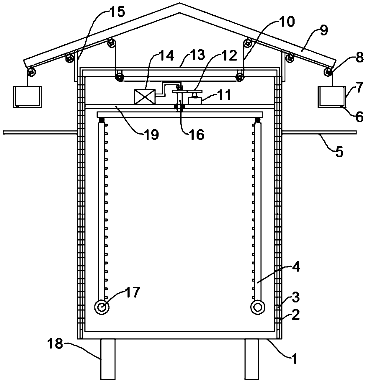
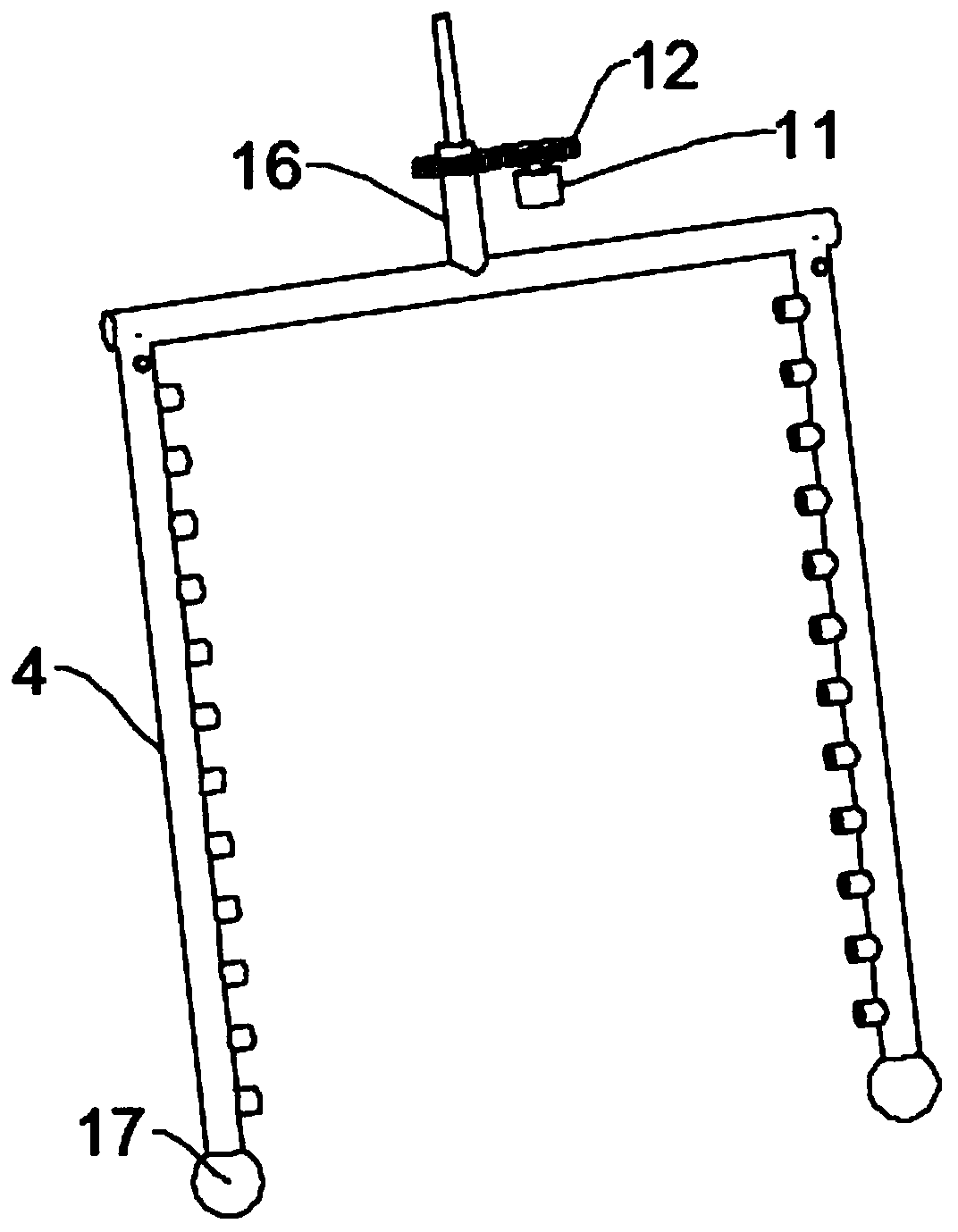
[0025] see Figure 1~2 , in an embodiment of the present invention, a signal machine for road traffic control, including a box body 1 and electronic components installed in the box body 1, the bottom of the box body 1 is evenly and symmetrically equipped with support legs 18, and the top of the box body 1 is installed There is a rain shield 9. In this embodiment, the rain shield 9 is preferably inverted V-shaped, and the rain shield 9 is fixedly connected to the box body 1 through the support rod 15 at the top of the side wall of the box body 1. The box body 1 Ventilation holes are provided on both side walls, and a heat dissipation mechanism is provided in the box body 1, and the heat dissipation mechanism includes a T-shaped tube 16, a driving mechanism for driving the T-shaped tube 16 to rotate at a variable speed, a heat dissipation pipe 4 and a heat dissipation fan 14. The T-shaped pipe 16 is installed on the upper part of the inner cavity of the box body 1 through the in...

Embodiment 2

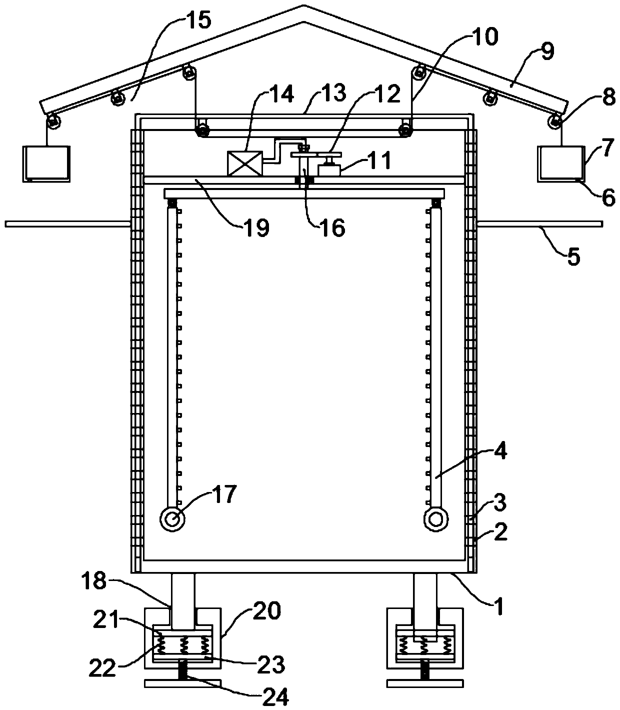
[0028] see image 3 The difference between this embodiment of the present invention and Embodiment 1 is that a shock absorbing mechanism is installed at the bottom end of the support leg 18, and the shock absorbing mechanism includes a shock absorbing base 20 and a shock absorbing spring 22, and the shock absorbing base 20 There is a chamber inside, and the support leg 18 runs through the top of the shock-absorbing base 20 and extends into the chamber. The bottom of the support leg 18 is fixed with a support plate 21, and the bottom of the support plate 21 is evenly fixed with a plurality of shock-absorbing springs 22. The shock spring 22 is in contact with the base plate 23, the bottom of the base plate 23 is fixed with an adjusting screw 24, the bottom end of the adjusting screw 24 runs through the shock absorbing base 20 and extends to the bottom of the shock absorbing base 20, the adjusting screw 24 is threadedly connected with the shock absorbing base 20, adjusting The base...


PUM


Abstract

The invention discloses an annunciator for road traffic control. The device comprises a box body and electronic elements installed in the box body. Vent holes are formed in two side walls of the box body. A heat dissipation mechanism is arranged in the box body. The heat dissipation mechanism comprises a T-shaped pipe, a driving mechanism used for driving the T-shaped pipe to rotate at a variablespeed, a heat dissipation pipe and a heat dissipation fan. The device further comprises a protection mechanism. The protection mechanism comprises a rain collection box, a pull rope and a protection cover. The device is provided with a heat dissipation mechanism. The T-shaped pipe drives the heat dissipation pipe to rotate at a variable speed, and the angle of the heat dissipation pipe is continuously changed under the condition that centrifugal force is continuously changed, so that the air blowing heat dissipation angle of a nozzle is continuously changed, and heat dissipation is more sufficient and uniform. A protection mechanism is arranged, so that rainwater cannot enter the box body through the heat dissipation holes to wet the electronic elements. When a fire breaks out in the box body, the interior of the whole box body is in a closed oxygen-deficient state, and larger accidents caused by fire spreading are avoided.

Description

technical field [0001] The invention relates to the technical field of road traffic, in particular to a signal machine for road traffic control. Background technique [0002] Signal machine is the trackside basic equipment of railway and urban rail transit. In the railway signal system with ground signal as the main signal, the driver must write and operate according to the display of the signal machine; urban rail transit uses vehicle signal as the main signal, and the main line section is basically There is no signal machine, only the ground signal machine is set in the turnout section for the needs of shunting operations. [0003] There are a large number of electronic components installed in the signal machine. When the electronic components are working, they will emit a large amount of heat, which requires a heat dissipation mechanism to dissipate heat. The existing heat dissipation mechanism uses a fixed heat dissipation fan to blow and dissipate heat. Keep it fixed, ...

Claims


Application Information

Patent Timeline
Patent Type & Authority Applications(China)
IPC IPC(8): H05K5/02H05K5/03H05K7/20B61L5/12F16F15/067
CPCH05K7/20863H05K5/0213H05K5/0217H05K5/03B61L5/125F16F15/067
Inventor 陈广柱
Owner 陈广柱
Why Eureka
Try Eureka