Livestock feed casting device and livestock feed casting method

A livestock and feed technology, used in animal feeding devices, animal husbandry, non-electric variable control, etc., can solve the problems of excessive feeding, deterioration, and waste of feed, and reduce the waste of feed and the possibility of deterioration. , to avoid the effect of overfeeding

Pending Publication Date: 2020-04-28
MIAOZHEN INFORMATION TECH CO LTD
View PDF8 Cites 0 Cited by
  • Summary
  • Abstract
  • Description
  • Claims
  • Application Information

AI Technical Summary

Problems solved by technology

[0003] At present, most of the feed feeding devices for livestock usually feed a large amount of feed at one time or feed the feed when the livestock is close to each other, and these two feed feeding methods are likely to cause overfeeding of the feed, resulting in Feed is wasted or spoiled

Method used


Image

  • Livestock feed casting device and livestock feed casting method
  • Livestock feed casting device and livestock feed casting method
  • Livestock feed casting device and livestock feed casting method

Examples


Embodiment 1

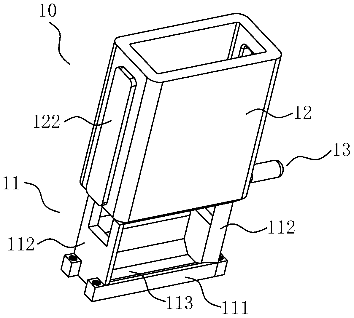
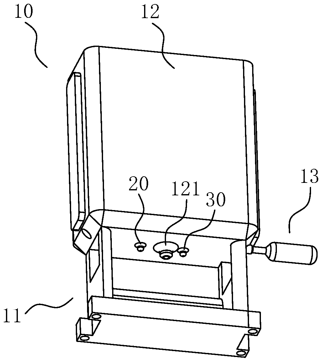
[0047] see figure 1 with figure 2 , figure 1 with figure 2 Schematic diagrams of the structure of the feed feeding device for livestock from different perspectives provided in the embodiments of the present application.

[0048] The livestock feed feeding device of the embodiment of the present application includes a livestock feed feeding mechanism 10, a livestock sensor 20, a trough inventory sensor 30 and a control module (not shown in the figure),

[0049] The livestock feed feeding mechanism 10 includes a trough 113 and a discharge port 121, and the discharge port 121 is provided with a discharge valve (not shown in the figure);

[0050] The livestock sensor 20 is arranged on the livestock feed feeding mechanism 10, and is used to sense whether there are livestock in the target feeding area;

[0051] The trough inventory sensor 30 is located on the livestock feed feeding mechanism 10, and is used to sense the feed inventory of the trough 113;

[0052] The control m...

Embodiment 2

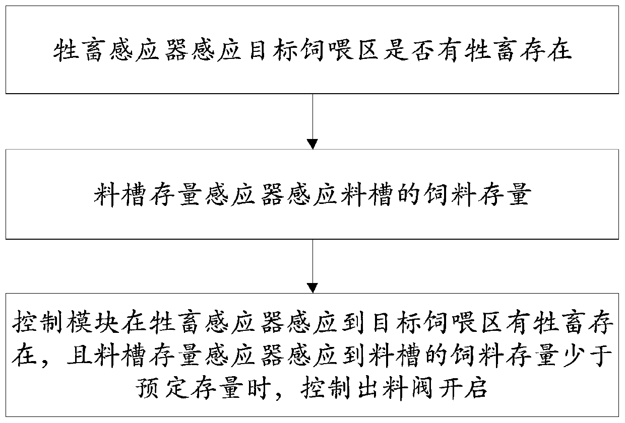
[0078] see Figure 1 to Figure 3 ,in, figure 1 with figure 2 Schematic diagram of the structure of the livestock feed feeding device under different perspectives provided by the embodiment of the present application, image 3 It is a schematic flow chart of the livestock feed feeding method provided in Example 2 of the present application.

[0079] The embodiment of the present application provides a livestock feed feeding method, which is applied to the livestock feed feeding device in the first embodiment above.

[0080] For the content of the feed feeding device for livestock in the embodiment of the present application, reference may be made to the specific content of the first embodiment above, and details are not repeated here.

[0081] The livestock feed feeding method of the embodiment of the present application includes:

[0082] Livestock sensor 20 senses whether there are livestock in the target feeding area;

[0083] Feed tank stock sensor 30 induction feed s...


PUM


Abstract

The invention provides a livestock feed casting device and a livestock feed casting method. The livestock feed casting device comprises a livestock feed casting mechanism, a livestock sensor, a feed trough stock sensor and a control module, wherein the livestock feed casting mechanism comprises a feed trough and a discharge hole; a discharge valve is arranged at the discharge hole; the livestock sensor is used for sensing whether livestock exists in a target feeding zone or not; the feed trough stock sensor is used for sensing the feed stock of a feed trough; the control module is used for controlling the discharge valve to be opened when the livestock sensor senses that the livestock exists in the target feeding zone and the feed trough stock sensor senses that the feed stock of the feedtrough is less than a preset stock. By adopting the livestock feed casting device and the livestock feed casting method provided by the invention, the feed stock of the feed trough is sensed by the feed trough stock sensor, and a feed is cast by the livestock feed casting device only when the livestock exists in the target feeding zone and the feed stock of the feed trough is less than the presetstock, so that excessive casting of the feed can be avoided.

Description

technical field [0001] The present application relates to the technical field of livestock feeding, in particular, to a livestock feed feeding device and a livestock feed feeding method. Background technique [0002] With the continuous development of the livestock breeding industry, people pay more and more attention to the hygiene and quality of the feed, because the hygiene and quality of the feed affect the parameters of the livestock during the growth period, and the hygiene and quality of the feed can make the meat of the livestock Quality improved. [0003] At present, most of the feed feeding devices for livestock usually feed a large amount of feed at one time or feed the feed when the livestock is close to each other, and these two feed feeding methods are likely to cause overfeeding of the feed, resulting in Feed is wasted or spoiled. Contents of the invention [0004] The purpose of the embodiments of the present application is to provide a livestock feed fee...

Claims


Application Information

Patent Timeline
Patent Type & Authority Applications(China)
IPC IPC(8): A01K5/02A01K39/012G05D9/12
CPCA01K5/02A01K39/0125G05D9/12
Inventor 邓来明吴明辉刘成鹏
Owner MIAOZHEN INFORMATION TECH CO LTD
Why Eureka
Try Eureka