
Construction waste crushing treatment machine

A construction waste and machine technology, applied in the field of construction waste crushing and processing machines, can solve the problems of easy blockage of crushed stones, high equipment maintenance, and single crushing method, and achieve the effect of improving the effect, reducing the maintenance cost, and smoothing the crushing process.

Inactive Publication Date: 2020-04-28
宣城久悠谷电子科技有限公司
View PDF10 Cites 0 Cited by
  • Summary
  • Abstract
  • Description
  • Claims
  • Application Information

AI Technical Summary

Problems solved by technology

[0003] However, a kind of construction waste crushing and processing machine in the current market has the following problems during use. a. The crushing method of the existing construction waste crushing and processing machines is relatively simple, and the crushed stones are placed in a fixed crushing area , the independent crushing work is carried out by the crushing rod, so that some larger crushed stones cannot enter the crushing area. At the same time, the contact between the crushed stones and the crushing roller is not sufficient, and the crushing effect is not good. The crushed stones are easy to block, which leads to the unsmooth operation of the device; b. The crushing rollers in the existing construction waste crushing and processing machines are all made of a whole. When a part of the crushing roller is damaged, it needs to be replaced as a whole, resulting in The maintenance cost of the device is too high

Method used


Image

  • Construction waste crushing treatment machine
  • Construction waste crushing treatment machine
  • Construction waste crushing treatment machine

Examples


Embodiment Construction

[0026] The embodiments of the present invention will be described in detail below with reference to the accompanying drawings, but the present invention can be implemented in many different ways defined and covered by the claims.

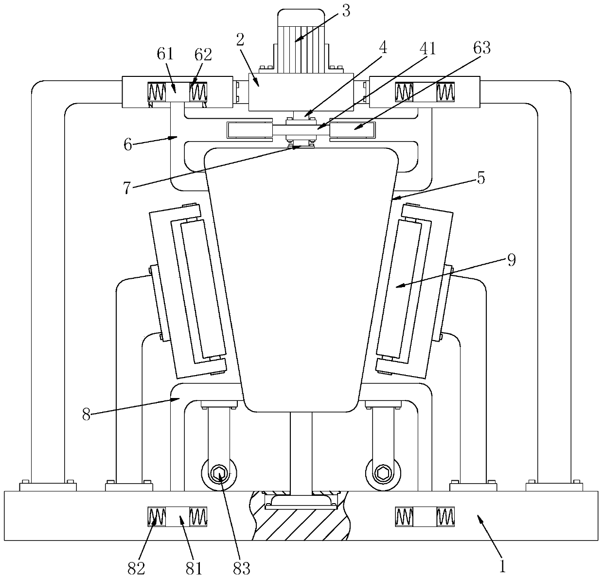
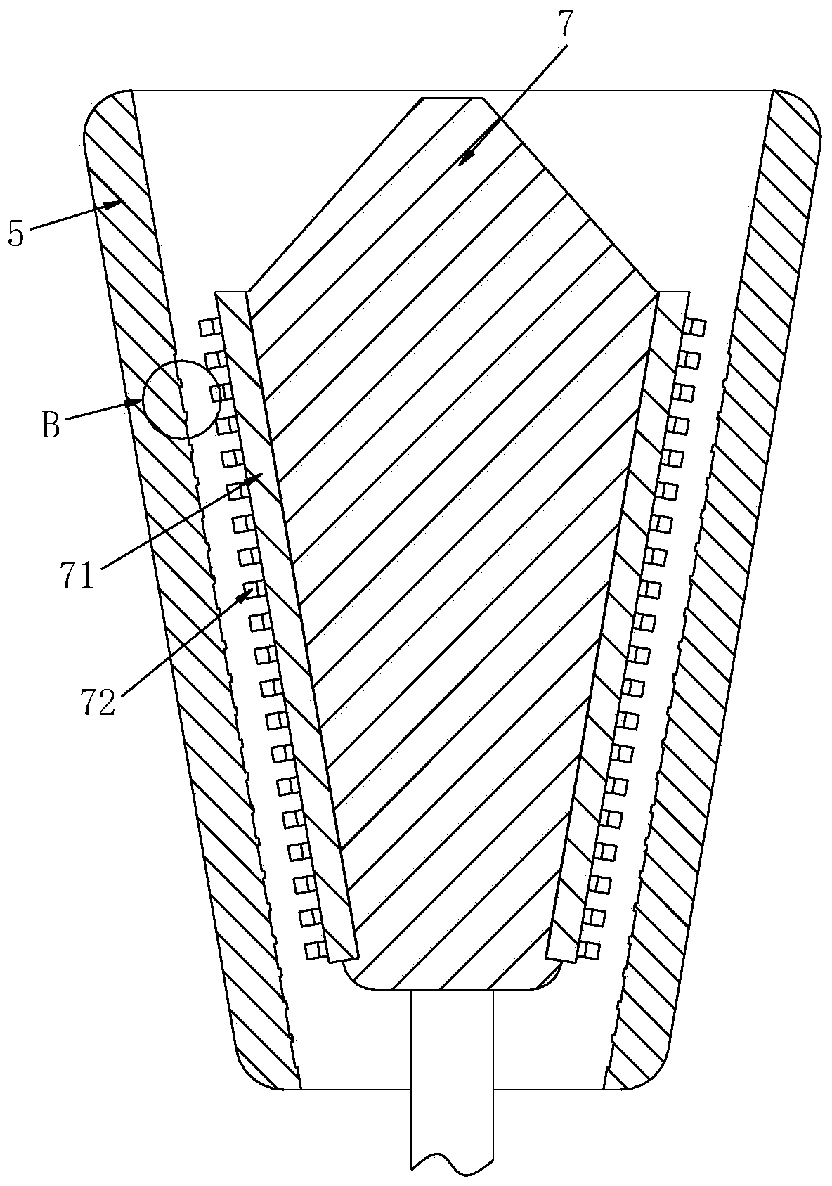
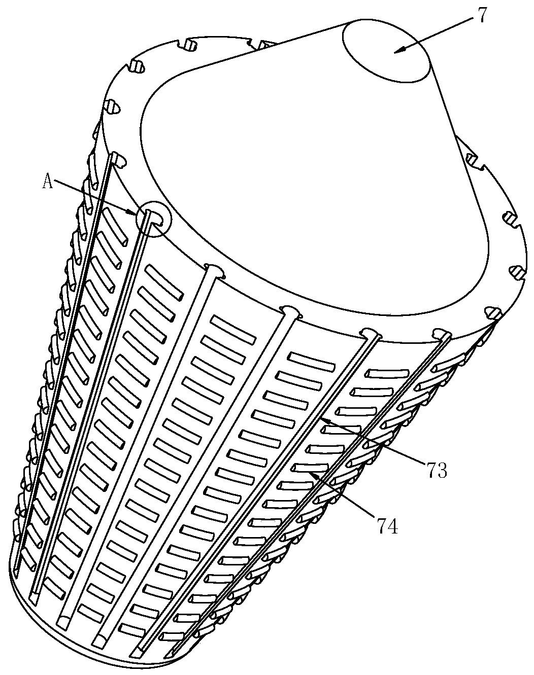
[0027] Such as Figure 1 to Figure 8 As shown, a construction waste crushing and processing machine includes a base 1, a first support 2, a drive motor 3, a drive shaft 4, a cone-shaped crushing cylinder 5, a second support 6, a crushing roller 7, a third support 8 and a limit position Roller 9, the first bracket 2 is installed on the upper end of the base 1, the drive motor 3 is installed at the top center of the first bracket 2, the output shaft of the drive motor 3 is connected with the drive shaft 4 through the connecting shaft, and the bottom of the drive shaft 4 A crushing roller 7 is connected, and the center of the bottom of the crushing roller 7 is connected with a rotating shaft. The rotating shaft is installed on the inner center of the b...


PUM


Abstract

The invention relates to a construction waste crushing treatment machine. The construction waste crushing treatment machine comprises a base, a first support, a driving motor, a driving shaft, a circular-truncated-cone-shaped crushing cylinder, a second support, a crushing roller, a third support and a limiting roller, the first support is installed at the upper end of the base, the driving motoris installed in the center of the top of the first support, an output shaft of the driving motor is connected with the driving shaft through a connecting shaft, the bottom of the driving shaft is connected with the crushing roller, the center of the bottom of the crushing roller is connected with a rotating shaft, the rotating shaft is installed in the center of the interior of the base through ashaft seat, the circular-truncated-cone-shaped crushing cylinder is arranged on the outer side of the crushing roller, the second support is welded to the outer wall of the upper end of the circular-truncated-cone-shaped crushing cylinder, the third support is welded to the outer wall of the lower end of the circular-truncated-cone-shaped crushing cylinder, and sliding grooves are formed in the joint of the second support and the first support and the joint of the third support and the base correspondingly. The construction waste crushing treatment machine has the characteristics of good crushing effect, wide application range, continuous and smooth crushing process and low maintenance cost.

Description

technical field [0001] The invention relates to the technical field of construction waste processing machinery, in particular to a construction waste crushing processing machine. Background technique [0002] Construction waste refers to the general designation of muck, waste concrete, waste masonry and other waste generated in the production activities of people engaged in demolition, construction, decoration, repair and other construction industries. According to the classification of generation sources, construction waste can be divided into engineering dregs, decoration waste, demolition waste, engineering mud, etc.; Mortar, mud, asphalt block, waste plastic, waste metal, waste bamboo and wood, etc. These materials are of no help to the building itself, but they are substances produced during the construction process and need to be treated accordingly in order to achieve the ideal project construction. The construction waste crushing machine is a kind of machinery that...

Claims


Application Information

Patent Timeline
Patent Type & Authority Applications(China)
IPC IPC(8): B02C4/28B02C4/30B02C4/00
CPCB02C4/00B02C4/28B02C4/30
Inventor 陈思霆
Owner 宣城久悠谷电子科技有限公司
Learn More