
Numerically-controlled lathe automatic puller with impact buffering function

A technology for buffering impact on CNC lathes, applied in the field of machinery, can solve problems such as large damage to bar blanks, damage to pullers, poor straightness of CNC lathe tool holders, etc., to achieve simple and practical structure, reduce impact, and avoid straightness reduction Effect

Pending Publication Date: 2020-04-28
大连长丰实业总公司
View PDF0 Cites 0 Cited by
  • Summary
  • Abstract
  • Description
  • Claims
  • Application Information

AI Technical Summary

Problems solved by technology

[0002] In industrialized mass production, when large quantities of blanks are continuously processed on CNC lathes, after a part is processed, it is necessary to manually pull out a certain length of the blank from the bar, and then proceed to the next step after the spindle chuck is clamped. In the processing of parts, the efficiency of manual extraction is low
When the traditional automatic puller for CNC lathe is used, the splint of the puller is in hard contact with the bar blank, which will cause great damage to the bar blank. The puller is often damaged or the straightness of the CNC lathe tool holder is out of tolerance

Method used

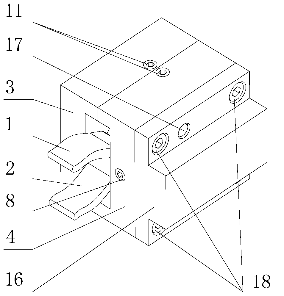
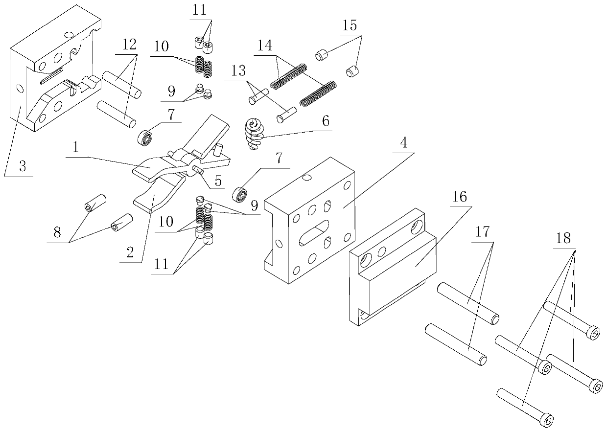

Image

  • Numerically-controlled lathe automatic puller with impact buffering function
  • Numerically-controlled lathe automatic puller with impact buffering function
  • Numerically-controlled lathe automatic puller with impact buffering function

Examples


Embodiment Construction

[0048] The present invention will be described in detail below with reference to the accompanying drawings and examples.

[0049] This embodiment provides an automatic puller for a CNC lathe with a function of buffering shocks, see the attached Figure 1-2, including: a housing, a clamp arm, a bearing 7, an elastic shaft 12, a first buffer assembly and a second buffer assembly;

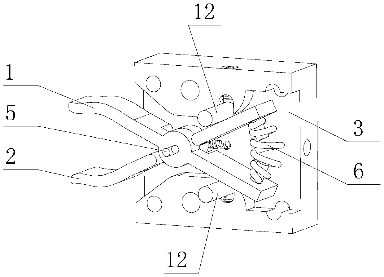
[0050] See attached image 3 , the clamp arm includes: a left clamp arm 1, a right clamp arm 2, a mandrel 5 and a bending spring 6;

[0051] The left jig arm 1 is composed of a stepped cylinder and a straight plate and a curved plate integrally formed on the outer circumference of the large diameter end of the stepped cylinder; an axial through hole is processed on the stepped cylinder; the straight plate and the curved plate They are respectively located on two opposite sides of the stepped cylinder; the straight plate is provided with a connecting head connected with the curved spring 6;

[0052]...


PUM


Abstract

The invention discloses a numerically-controlled lathe automatic puller with an impact buffering function. The numerically-controlled lathe automatic puller comprises a shell, a clamping arm, a bearing, springing shafts, a first buffering assembly and a second buffering assembly, the clamping arm is of an X-shaped structure formed by connecting two plates in a pin joint mode, the two side faces ofone end of the X-shaped structure are bent plates, a spring is installed between the two side plates of the other end of the X-shaped structure, an installation hole for mounting the clamping arm isformed in the shell, the two ends of a hinge pin of the clamping arm are installed in the shell through bearings respectively, then the clamping arm is installed in the installation hole of the shell,the first buffering assembly is installed in the shell, the two or more springing shafts are mounted in kidney-shaped through holes formed in the shell separately, the axes of the springing shafts are parallel to the axis of the hinge pin of the clamping arm, and the second buffering assembly is mounted in the shell. According to the numerically-controlled lathe automatic puller, a bar blank canbe automatically pulled out by the set length, the impact buffering function is achieved, and damage to the bar blank, the puller or a tool rest of a numerical control lathe is prevented.

Description

technical field [0001] The invention belongs to the technical field of machinery, and in particular relates to an automatic puller for a numerically controlled lathe with the function of buffering impact. Background technique [0002] In industrialized mass production, when a large number of blanks are continuously processed on a CNC lathe, after processing a part, it is necessary to manually pull out a certain length of the blank from the bar, and then proceed to the next one after the spindle chuck is clamped. The processing of parts and manual extraction are inefficient. When the traditional CNC lathe automatic puller is used, the splint of the puller is in hard contact with the bar blank, which will cause great damage to the bar blank. The puller is often damaged or the straightness of the CNC lathe tool holder is out of tolerance. Contents of the invention [0003] In view of this, the present invention provides an automatic puller for a CNC lathe with the function o...

Claims


Application Information

Patent Timeline
Patent Type & Authority Applications(China)
IPC IPC(8): B23Q7/04B23Q7/06B23B15/00
CPCB23Q7/06B23Q7/042
Inventor 王泽亮仇红伟王洋武耀德唐福莹孙玉庆牟津瑶
Owner 大连长丰实业总公司
Learn More