Pneumatic motor side polishing base

A technology of air motor and card holder, which is applied in the direction of grinding drive device, grinding/polishing equipment, surface polishing machine tool, etc., can solve the problem of uneven rotation, excessive vibration, low product yield and product yield, etc. problem, to achieve the effect of excellent effect, guaranteed reliability, stable and efficient output

Pending Publication Date: 2020-04-28
DONGGUAN LINGJIE PRECISION MACHINING TECH CO LTD
View PDF0 Cites 0 Cited by
  • Summary
  • Abstract
  • Description
  • Claims
  • Application Information

AI Technical Summary

Problems solved by technology

At present, most of the polishing equipment is single polishing wheel hand-held product polishing. Due to the limitation of the skill level of the operators, the product output rate and product yield rate after polishing are low.
In order to improve the efficiency of the existing polishing equipment, the designed fixture is a side throwing fixture driven by the polishing wheel. During the polishing process, the product needs to be driven by the polishing wheel, resulting in excessive vibration and uneven rotation during the production process, resulting in product removal. The amount is unstable, and the side polishing effect is not good; and this polishing process has a great impact on the size and appearance yield of the finished product, and the product polishing cost is high
Especially for small-sized hardware parts, due to product features and high requirements for appearance, there is currently no corresponding reliable processing solution

Method used


Image

  • Pneumatic motor side polishing base
  • Pneumatic motor side polishing base
  • Pneumatic motor side polishing base

Examples


Embodiment Construction

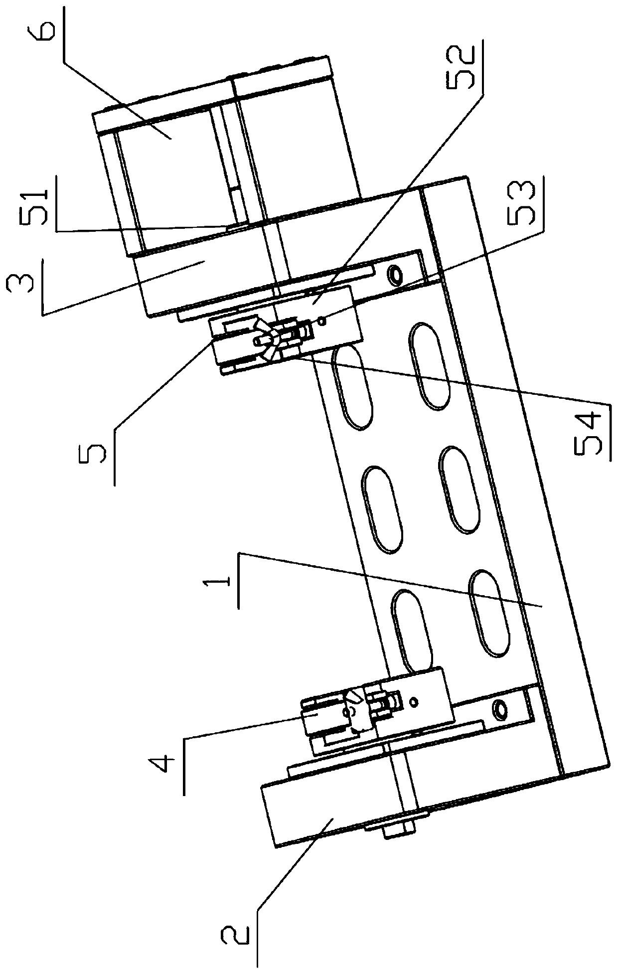
[0019] The present invention will be described in detail below in conjunction with the implementations shown in the drawings, but it should be noted that these implementations are not limitations of the present invention, and those of ordinary skill in the art based on the functions, methods or structures of these implementations, etc. Effective transformation or substitution all belong to the protection scope of the present invention.

[0020] In the description of the present invention, it should be noted that unless otherwise specified and limited, the terms "installation", "connection" and "connection" should be understood in a broad sense, for example, it can be a mechanical connection or an electrical connection, or it can be two The internal communication of each element may be directly connected or indirectly connected through an intermediary, and those skilled in the art can understand the specific meaning of the terms according to specific situations.

[0021] like ...


PUM


Abstract

The invention discloses a pneumatic motor side polishing base. The base comprises a mounting base, a first baffle, a second baffle, a first rotary clamping part, a second rotary clamping part and a driving part; the first baffle is arranged at one end of the mounting base; the second baffle is arranged at the other end of the mounting base; the first rotary clamping part is arranged on the first baffle; the second rotary clamping part is arranged on the second baffle; the first rotary clamping part and the second rotary clamping part are oppositely arranged; and the driving part is connected with the second rotary clamping part and drives the second rotary clamping part to rotate. The pneumatic motor side polishing base is reasonable in structure, good in polishing appearance effect, stable in surface removing amount, high in production efficiency and high in yield.

Description

technical field [0001] The invention relates to the field of grinding and polishing equipment, and more specifically relates to a side throwing base of an air motor. Background technique [0002] When polishing hardware in the prior art, polishing equipment is used. At present, most of the polishing equipment is a single polishing wheel for handheld product polishing. Due to the limitation of the skill proficiency of the operators, the product output rate and product yield rate after polishing are low. In order to improve the efficiency of the existing polishing equipment, the designed fixture is a side throwing fixture driven by the polishing wheel. During the polishing process, the product needs to be driven by the polishing wheel, resulting in excessive vibration and uneven rotation during the production process, resulting in product removal. The amount is unstable, and the side polishing effect is not good; and this polishing process has a great impact on the size and a...

Claims


Application Information

Patent Timeline
Patent Type & Authority Applications(China)
IPC IPC(8): B24B29/02B24B27/00B24B41/06B24B47/14
CPCB24B27/0023B24B29/02B24B41/06B24B47/14
Inventor 叶兴基
Owner DONGGUAN LINGJIE PRECISION MACHINING TECH CO LTD
Why Eureka
Try Eureka