
Full-automatic heat-shrinkable pipe jacketing machine and heat-shrinkable pipe jacketing method

A heat-shrinkable tube and sleeve machine technology, used in metal processing and other directions, can solve the problems of poor wire terminal coating quality, inability to guarantee heat-shrinkable tubes, low production efficiency, etc. The effect of improving casing accuracy

Pending Publication Date: 2020-04-28
XIAMEN HIPRECISE TECH CO LTD
View PDF0 Cites 3 Cited by
  • Summary
  • Abstract
  • Description
  • Claims
  • Application Information

AI Technical Summary

Problems solved by technology

[0003] The traditional heat-shrinkable tubing work is done manually, which has low production efficiency and high labor costs. Therefore, there are highly automated heat-shrinkable tubing machines on the market.
However, in the heat-shrinkable tube in the related art, the coating quality of the heat-shrinkable tube on the wire terminal is poor, and it is impossible to ensure that the nozzle of the heat-shrinkable tube is flush with the end face of the terminal, and there is a large error

Method used

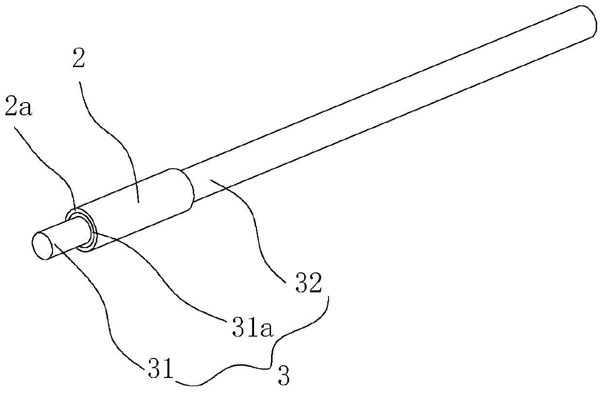
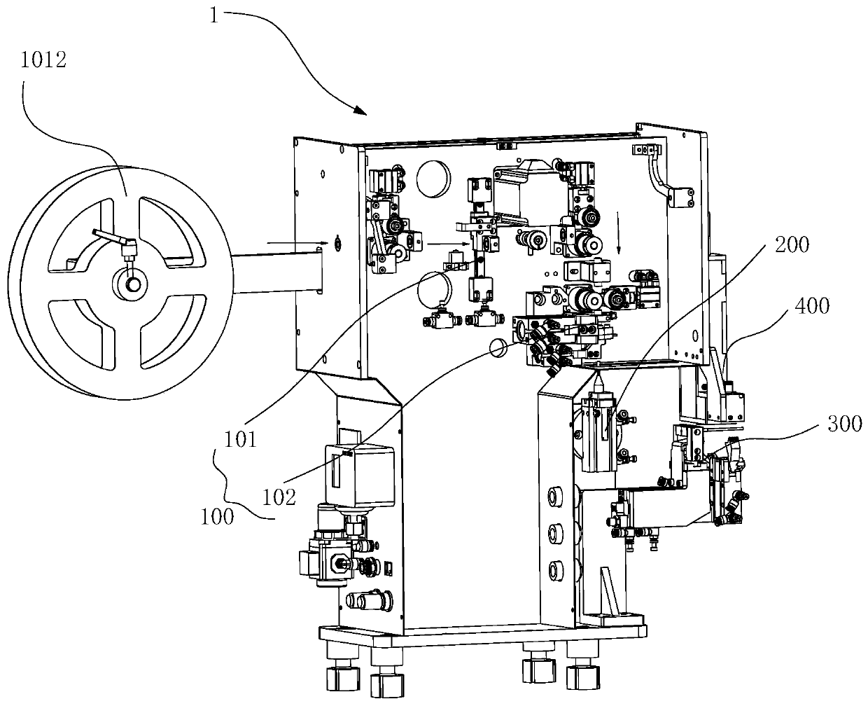
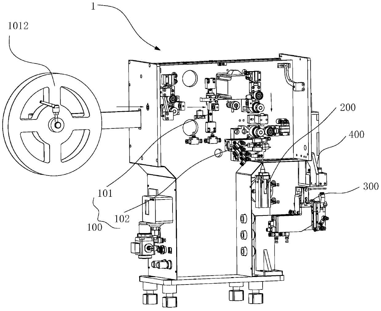

Image

  • Full-automatic heat-shrinkable pipe jacketing machine and heat-shrinkable pipe jacketing method
  • Full-automatic heat-shrinkable pipe jacketing machine and heat-shrinkable pipe jacketing method
  • Full-automatic heat-shrinkable pipe jacketing machine and heat-shrinkable pipe jacketing method

Examples


Embodiment Construction

[0051] Embodiments of the present invention are described in detail below, examples of which are shown in the drawings, wherein the same or similar reference numerals designate the same or similar elements or elements having the same or similar functions throughout. The embodiments described below by referring to the figures are exemplary and are intended to explain the present invention and should not be construed as limiting the present invention.

[0052] In order to better understand the above technical solutions, the following will describe exemplary embodiments of the present invention in more detail with reference to the accompanying drawings. Although exemplary embodiments of the present invention are shown in the drawings, it should be understood that the invention may be embodied in various forms and should not be limited to the embodiments set forth herein. Rather, these embodiments are provided for more thorough understanding of the present invention and to fully c...


PUM


Abstract

The invention provides a full-automatic heat-shrinkable pipe jacketing machine and a heat-shrinkable pipe jacketing method. The full-automatic heat-shrinkable pipe jacketing machine comprises a heat-shrinkable pipe feeding part, a heat-shrinkable pipe transferring part, a pipe penetrating part and a hot air flow supply part, wherein the heat-shrinkable pipe feeding part is suitable for supplying aheat-shrinkable pipe; the heat-shrinkable pipe transferring part is provided with a fixing rod; the fixing rod is suitable for fixing the heat-shrinkable pipe and transferring the heat-shrinkable pipe to a predetermined pipe penetrating position; the pipe penetrating part is provided with a clamping channel; a first opening of the clamping channel allows a wire harness to be inserted into; a second opening of the clamping channel allows the fixing rod to be pulled out; through holes communicating with the outside are formed in the clamping channel; a limiting unit is arranged on the second opening and is used for limiting the heat-shrinkable pipe at the pipe penetrating position when the fixing rod leaves the clamping channel and feeding and inserting the wire harness into the heat-shrinkable pipe at the pipe penetrating position until a terminal of the wire harness penetrates out of the second opening; hot air flow is supplied into the clamping channel through the through holes, so that the wire harness is fixedly connected with the heat-shrinkable pipe; and the hot air flow supply part is used for supplying the hot air flow to the pipe penetrating part. Therefore, the coating quality of the heat-shrinkable pipe to a conductor terminal can be improved, and the jacketing precision of the heat-shrinkable pipe is improved.

Description

technical field [0001] The invention relates to the technical field of wire harness processing equipment, in particular to an automatic heat-shrinkable tube casing machine and a casing method. Background technique [0002] The heat-shrinkable tube of the distribution insulated wire is a necessary step in the processing and production of the distribution line. The heat-shrinkable tube is sleeved on the wire terminal, and it is heated and fastened, which can effectively insulate and protect the terminal and the wire. [0003] The traditional heat-shrinkable tubing work is done manually, which has low production efficiency and high labor costs. Therefore, there are highly automated heat-shrinkable tubing machines on the market. However, in the heat-shrinkable tube in the related art, the coating quality of the heat-shrinkable tube to the wire terminal is poor, and it is impossible to ensure that the nozzle of the heat-shrinkable tube is flush with the end surface of the termin...

Claims


Application Information

Patent Timeline
IPC IPC(8): B29C63/42B29C35/04B26D1/30B29C37/00B29C35/06
CPCB26D1/30B29C35/045B29C35/065B29C63/0004B29C63/42
Inventor 李普天钟胜斌付金勇张鹏志
Owner XIAMEN HIPRECISE TECH CO LTD
Learn More