Pattern printing device for ceramic cup

A technology for printing patterns and ceramic cups, applied in printing, printing machines, rotary printing machines, etc., can solve problems such as manual rotation, and achieve the effect of stable turning over and improving printing efficiency.

Active Publication Date: 2020-04-28
山东兆鼎瓷业有限公司
View PDF8 Cites 10 Cited by
  • Summary
  • Abstract
  • Description
  • Claims
  • Application Information

AI Technical Summary

Problems solved by technology

[0005] In order to overcome the shortcomings of requiring people to manually absorb printing pigments for printing and manually turning ceramic cups for printing, the tech

Method used


Image

  • Pattern printing device for ceramic cup
  • Pattern printing device for ceramic cup
  • Pattern printing device for ceramic cup

Examples


Embodiment 1

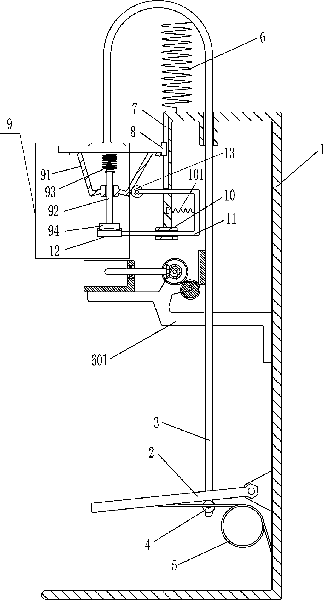
[0018] A ceramic cup printing pattern device, such as figure 1 As shown, it includes a bracket 1, a swing rod 2, a first slide rod 3, a first roller 4, a torsion spring 5, a return spring 6, a mounting rod 601, a slide rail 7, a slider 8, a fitting device 9, a second Sliding sleeve 10, first spring 101, third slide bar 11, material suction plate 12 and second roller 13, swing rod 2 is provided in the lower right side of the bracket 1, the bottom of the swing rod 2 is connected with the lower right side of the bracket 1 A torsion spring 5 is arranged between them, a mounting rod 601 is provided on the upper right side of the bracket 1, a container for placing a ceramic cup is provided on the left side of the top of the mounting rod 601, and a first sliding rod 3 is provided on the left side of the top wall of the bracket 1 A return spring 6 is provided between the inner upper part of the first slide bar 3 and the top of the bracket 1. The first slide bar 3 is located on the fro...

Embodiment 2

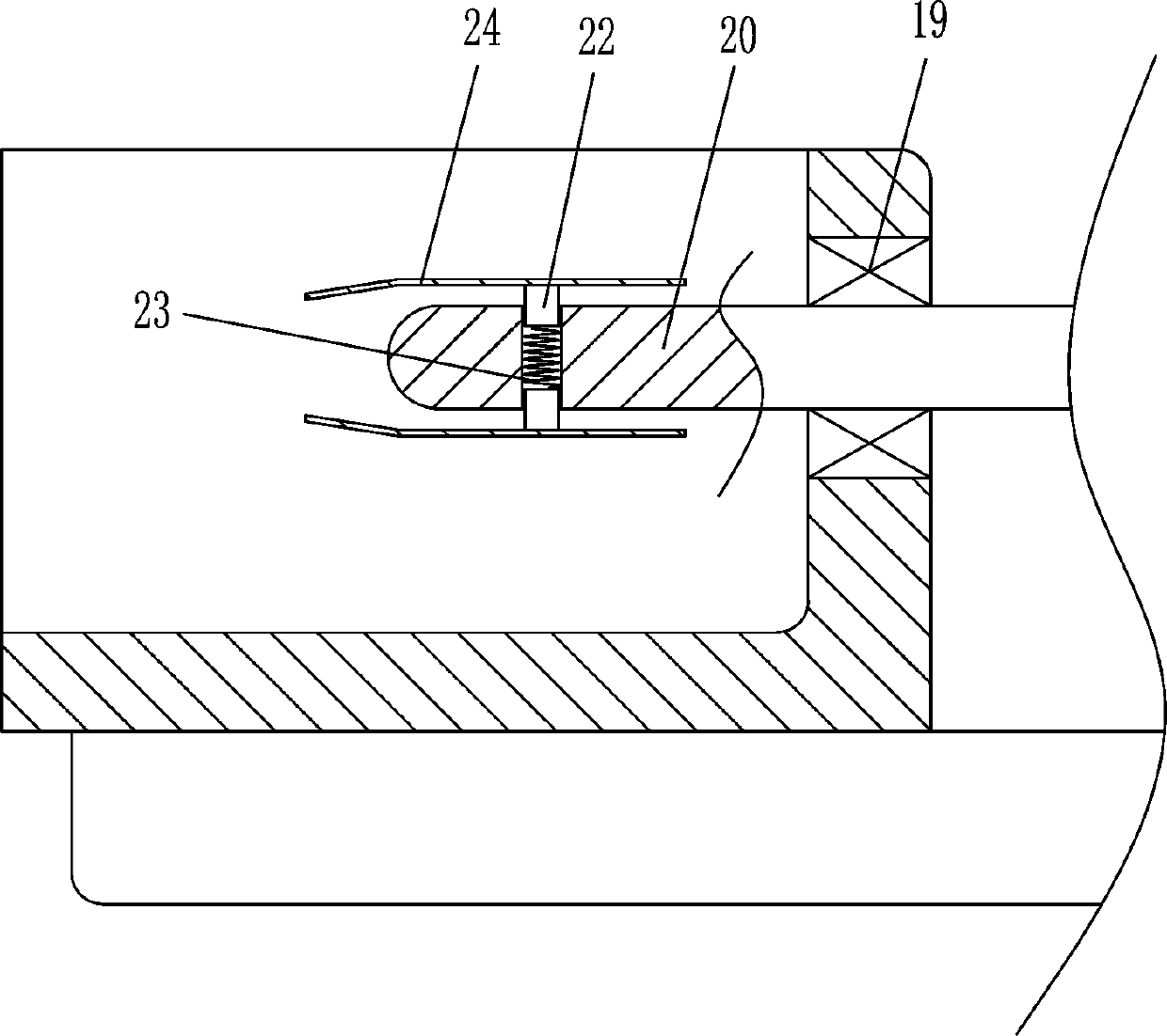
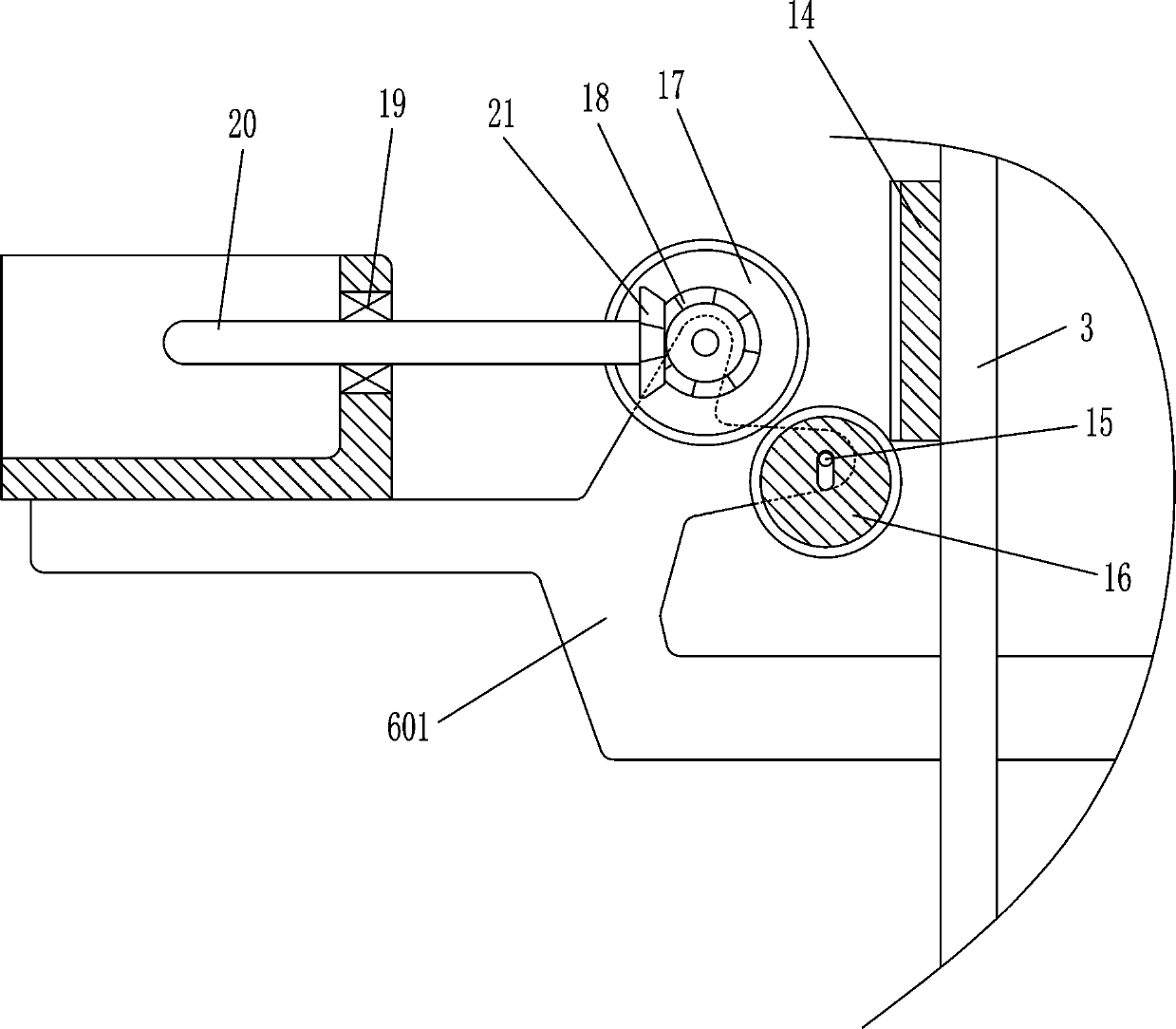
[0023] On the basis of Example 1, such as Figure 2-3 Shown, also comprise rack 14, pin rod 15, hollow gear 16, bull gear 17, first bevel gear 18, bearing 19, rotating rod 20 and second bevel gear 21, the left side of first slide bar 3 The top is provided with tooth bar 14, and the left part rotation type of mounting bar 601 is provided with pin bar 15, and pin bar 15 is provided with hollow gear 16, and the left part rotating type of mounting bar 601 is provided with bull gear 17, and bull gear 17 is positioned at On the left side of the hollow gear 16, the hollow gear 16 cooperates with the rack 14. The placement container installed on the mounting rod 601 is located on the left side of the bull gear 17. The front side of the bull gear 17 is provided with the first bevel gear 18, and the mounting rod 601 is installed Bearing 19 is installed in the middle part of the right wall of the placing container, and bearing 19 is provided with rotating rod 20, and rotating rod 20 righ...


PUM


Abstract

The invention relates to a pattern printing device, in particular to a pattern printing device for a ceramic cup. The pattern printing device for the ceramic cup can automatically adsorb printing pigment and automatically turn the ceramic cup over to conduct printing. The pattern printing device for the ceramic cup comprises a support, a swing rod, etc. The swing rod is rotationally arranged on the lower portion of the right side in the support. When the swing rod is stepped, the pattern printing device for the ceramic cup can automatically adsorb the pattern pigment to print a pattern on theceramic cup, and after pattern printing of the ceramic cup, the swing rod is stopped being stepped; the ceramic cup is put on a rotating rod in a sleeving mode so as to be automatically turned over with the printed side facing down through clockwise rotating of the rotating rod after printing of the ceramic cup for the first time; and therefore, the hands of a user can be freed, and the pattern printing efficiency can be improved.

Description

technical field [0001] The invention relates to a pattern printing device, in particular to a ceramic cup pattern printing device. Background technique [0002] Ceramic is a shape made of clay. It is made of clay or other inorganic non-metallic raw materials and processed by molding and sintering. It is used to decorate and protect the walls and floors of buildings. After drying, it is heated to a certain degree so that it hardens and is no longer soluble in water. [0003] After the ceramic cup is fired, it is necessary to print patterns on the outer wall of the ceramic cup to improve the appearance. However, the current printing method requires people to hold the sponge block with one hand. The sponge blocks are intermittently printed on the outer wall of the ceramic cup, and people need to rotate the ceramic cup to complete the pattern printing on the outer wall of the ceramic cup. In this way, it takes a long time to print the pattern on the entire ceramic cup, and the ...

Claims


Application Information

Patent Timeline
IPC IPC(8): B41F17/26
CPCB41F17/26
Inventor 蔡丽
Owner 山东兆鼎瓷业有限公司
Why Eureka
Try Eureka