Silicon ingot tipping gear

A turning device and silicon ingot technology, applied in the direction of hoisting device, hoisting device, etc., can solve the problems of high material damage rate, unguaranteed safety, low work efficiency, etc., and achieve the effect of smooth turning

Inactive Publication Date: 2011-05-25
王后忠
View PDF7 Cites 11 Cited by
  • Summary
  • Abstract
  • Description
  • Claims
  • Application Information

AI Technical Summary

Problems solved by technology

However, due to the characteristics of the silicon ingot material, the weight of the silicon ingot used is relatively large, manual turning is labor-intensive, low work efficiency, and safety cannot be guaranteed
However, using the existing driving equipment and other equipment to turn over will cause a high breakage rate of the material due to the brittleness of the silicon material.

Method used


Image

  • Silicon ingot tipping gear
  • Silicon ingot tipping gear
  • Silicon ingot tipping gear

Examples


Embodiment Construction

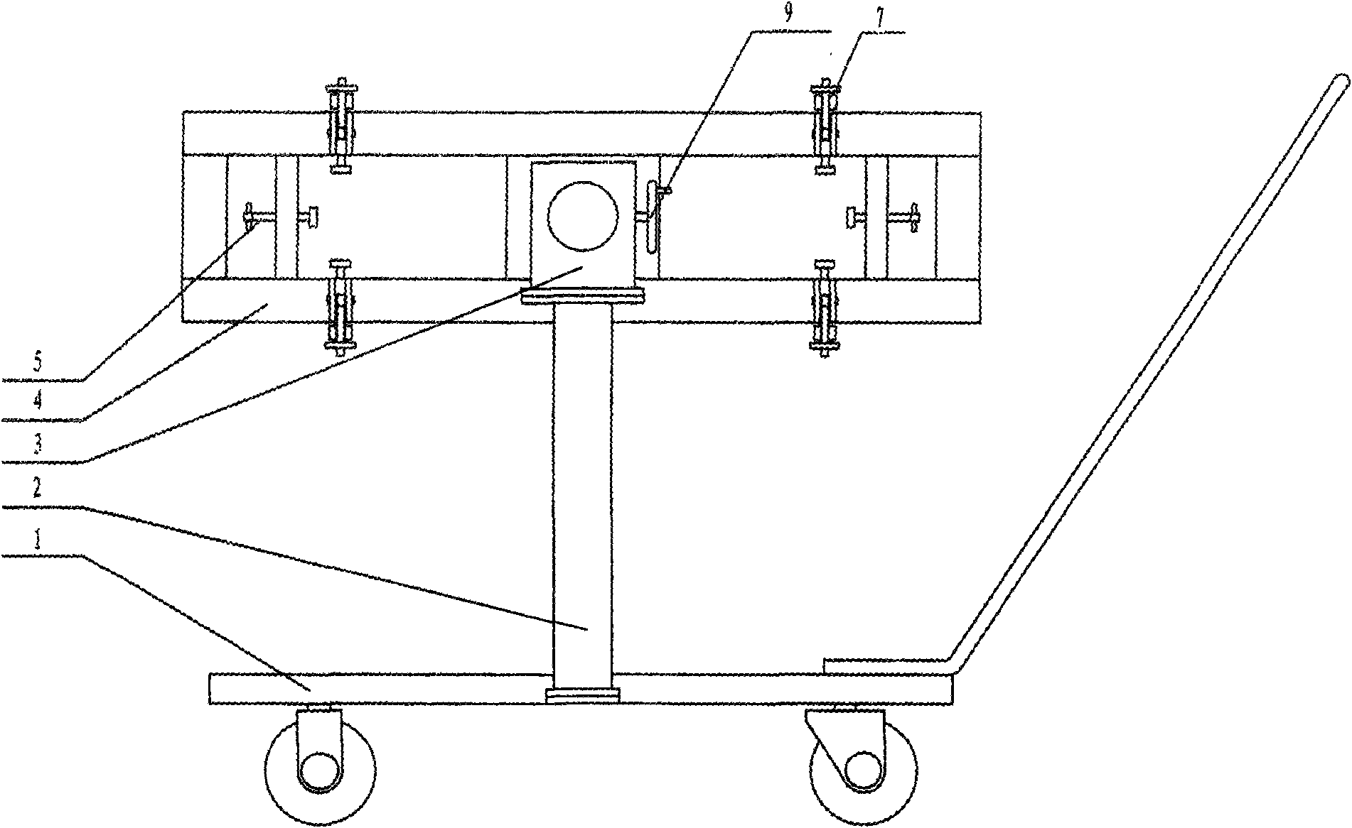
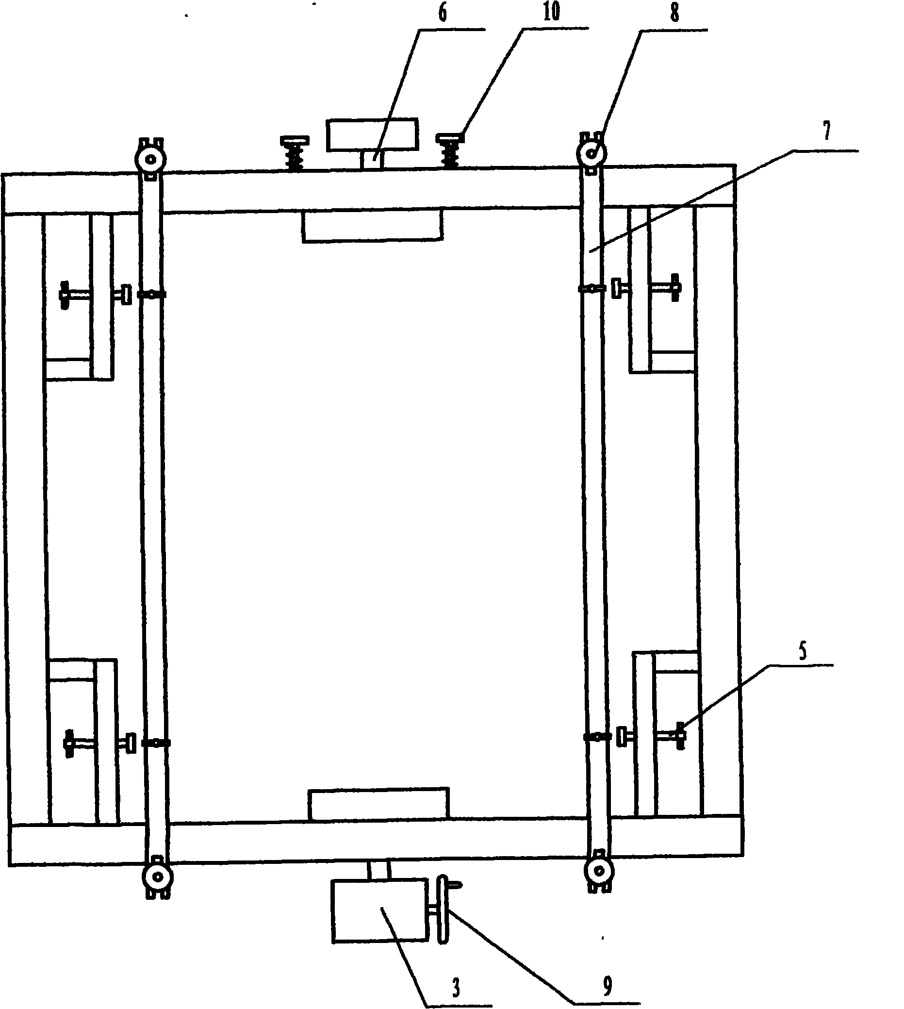
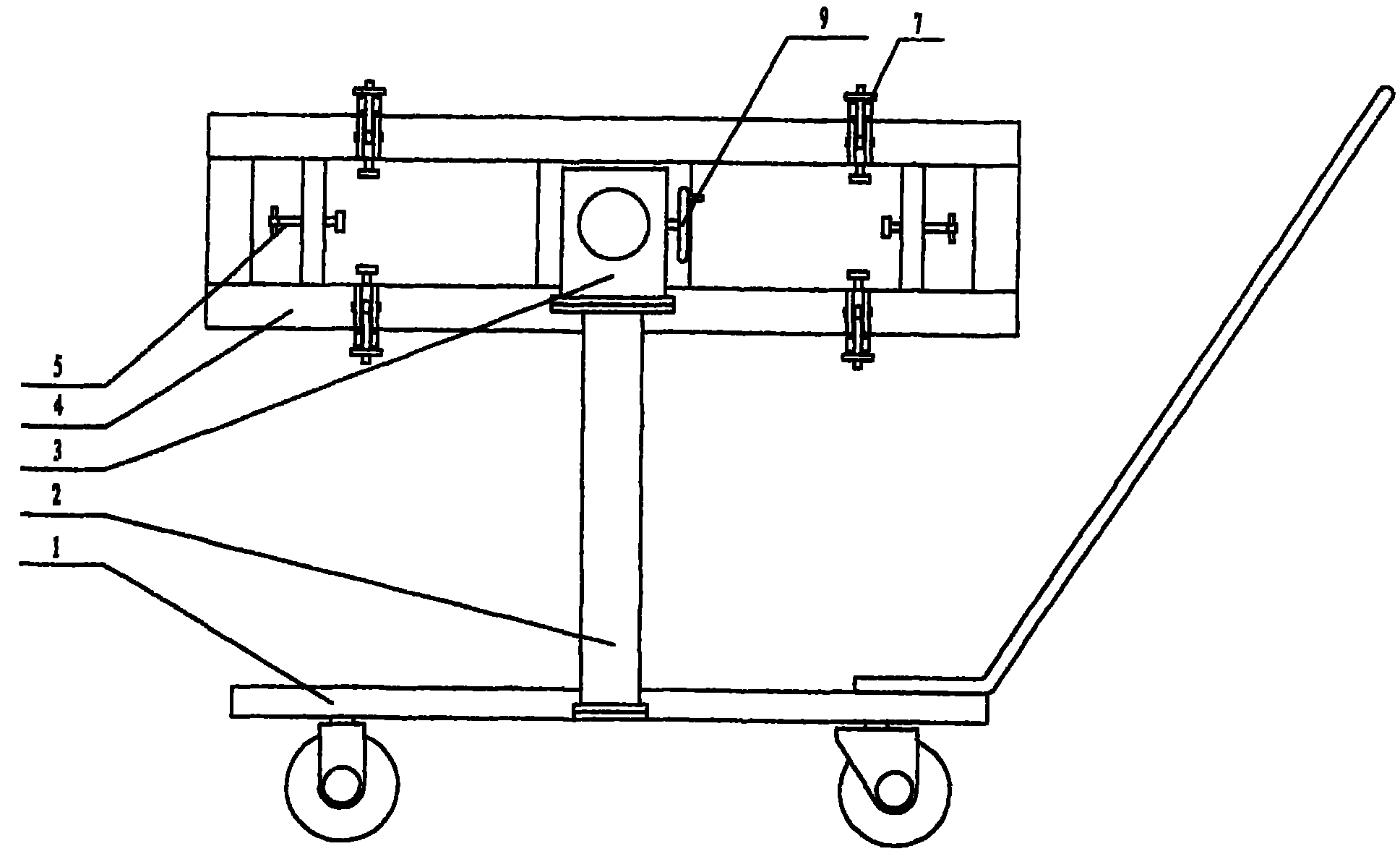
[0010] Such as figure 1 and figure 2 As shown, a silicon ingot turning device includes a loading trolley 1, a bracket 2 and a turning bracket 4, the bottom of the bracket 2 is fixed on the loading trolley 1, and the turning bracket 4 is movably connected with the bracket 2 through a rotating shaft 6, and the rotating shaft 6. One or two rotating shaft structures can be used. When two rotating shafts are used, each rotating shaft is respectively located at both ends of the bracket 2. When one rotating shaft is used, the whole body passes through the bracket 2, and the end of one side of the rotating shaft 6 extends out of the bracket 2. The outside is connected with the rotating mechanism. Described turning mechanism is made up of reduction box 3 and turning over handwheel 9, and turning over handwheel 9 is located on the reduction box 3 and links to each other with rotating shaft 6 through the reduction box 3 internal gears. The front and back sides of the overturning brack...


PUM


Abstract

The invention discloses a silicon ingot tipping gear. The silicon ingot tipping gear comprises a loading trolley (1), a bracket (2) and a tipping bracket (4), wherein the bottom of the bracket (2) is fixed on the loading trolley (1); the tipping bracket (4) is moveably connected with the bracket (2) through a spindle (6); one end of the spindle (6) extends out of the bracket (2) and then is connected with a rotating mechanism; the tipping bracket (4) is provided with compression bars (7); and the compression bars (7) are moveably installed on the tipping bracket (4) through compression bar hand wheels (8). The silicon ingot tipping gear has the advantages of simple structure, low labor intensity of manual tipping and high working efficiency, is convenient to operate and is not easy to damage silicon ingot materials.

Description

technical field [0001] The invention relates to a silicon ingot turning device. Background technique [0002] Silicon ingot is an important production raw material used in the production of photovoltaic cells in the new energy photovoltaic industry. Due to the limitations of the casting process of silicon ingots, the upper surface of silicon ingots has poor flatness and the surface contains many impurities and uneven hardness. Usually, the processing from the upper surface will cause uneven slices and waste products, resulting in waste of materials, resulting in slicing equipment. and tool damage. In order to overcome the above defects, the silicon ingot is often turned over and sliced ​​from the lower surface of the silicon ingot. However, due to the characteristics of the silicon ingot material and the heavy weight of the silicon ingot, manual turning is labor-intensive, low in work efficiency, and safety cannot be guaranteed. However, the use of existing equipment such...

Claims


Application Information

Patent Timeline
Patent Type & Authority Applications(China)
IPC IPC(8): B66F19/00
Inventor 王后忠孙鹏丁馨明
Owner 王后忠
Why Eureka
Try Eureka