Welding jig overturning method and device

A technology of welding fixtures and fixtures, which is applied in the direction of auxiliary devices, welding equipment, auxiliary welding equipment, etc., can solve the problems of unstable rotation, poor adjustment of impact force, and high failure rate, so as to improve the turning accuracy and turning speed, and be stable and reliable. The effect of flipping and high-precision flipping

Active Publication Date: 2014-06-18
广东泰格威机器人科技有限公司
View PDF10 Cites 11 Cited by
  • Summary
  • Abstract
  • Description
  • Claims
  • Application Information

AI Technical Summary

Problems solved by technology

Rotation at a certain angle can be achieved by using the divider, but when the divider is large, the failure rate is high due to the thin internal division structure. Therefore, this driving method is only suitable for turning over the fixture for processing small workpieces.
In the prior art, there are still shortcomings such as unstable rotation, poor adjustment of impact force and poor precision in the way of realizing the flipping of the clamp body.
[0004] Due to the limitations of the existing driving mode of welding fixture turning, it is difficult to meet the requirements of robot automatic welding. Therefore, it is necessary to provide an economical and practical welding fixture turning over, with high turning precision, stable and reliable turning and easy adjustment of turning speed. The method and the device used therefor reduce the use cost of robot automation welding and improve the welding quality, and then promote the welding application of robot automation

Method used


Image

  • Welding jig overturning method and device

Examples


Embodiment

[0032] In this embodiment, the flip angle set in the first stage is 100° as an example to describe the following.

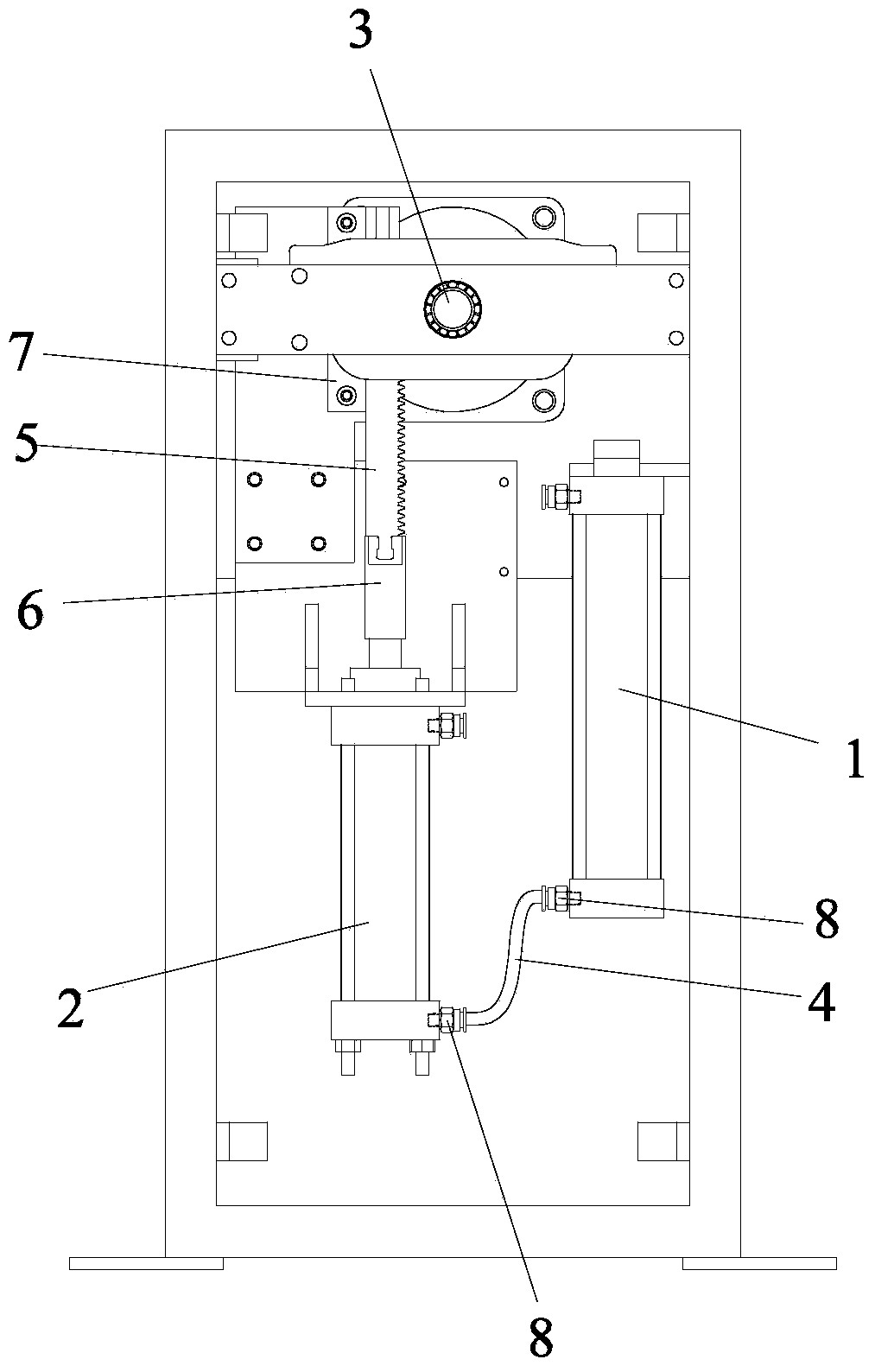
[0033] The method for turning over the welding fixture of the present invention is to control the rotating speed of the fixture main shaft 3 driving the turning of the fixture in stages through the combination of the cylinder 1 and the hydraulic cylinder 2, so as to realize the fast, stable and reliable turning of the welding fixture.

[0034] More specifically, the welding fixture flipping method includes the following two stages:

[0035] In the first stage, the compressed gas of cylinder 1 is used to push the oil in hydraulic cylinder 2, so that the hydraulic energy of hydraulic cylinder 2 can control the rotation speed of main shaft 3, and drive the fixture to turn over to the set turning angle θ; among them, the set turning angle θ is 100°.

[0036] The second stage: use the hydraulic energy of its own hydraulic cylinder 2 to control the rotation speed of the...

Embodiment 2

[0055] The only difference between this embodiment and the first embodiment is that the turning angle set in the first stage is 50°, and the method of turning over the welding jig and the devices used therefor are consistent with the first embodiment.

Embodiment 3

[0057] The only difference between this embodiment and the first embodiment is that the turning angle set in the first stage is 110°, and the method of turning over the welding jig and the devices used therefor are consistent with the first embodiment.


PUM


Abstract

The invention provides an economical and practical welding jig overturning method. The welding jig overturning method includes the step of conducting staging control over the rotating speed of a jig main shaft for driving a jig to be overturned to achieve overturning of the welding jig, wherein the staging control over the rotating speed of the jig main shaft for driving the jig to be overturned is characterized in that a combination of a pneumatic system and a hydraulic system is adopted to achieve the staging control over the rotating speed of the jig main shaft for driving the jig to be overturned. By means of the welding jig overturning method, the using cost of robot automation welding can be effectively reduced, the welding quality can be improved, and the welding jig overturning method is of great significance on popularizing robot automation welding. The invention further provides a welding jig overturning device, and the welding jig overturning device comprises a connecting mechanism and a driving mechanism for driving the connecting mechanism to further drive the jig to be overturned; the driving mechanism is composed of the hydraulic system and the pneumatic system in a connected mode. By means of the welding jig overturning device, the jig overturning accuracy is improved; meanwhile, the welding jig overturning device has the advantages of being simple in structure, convenient to operate and the like; the welding effectiveness and the welding accuracy of the jig can be guaranteed.

Description

technical field [0001] The invention relates to the technical field of welding processing machinery, and more specifically, relates to a method for turning over a welding fixture and a device used therefor. Background technique [0002] In order to improve the degree of robot welding automation and cost-effectiveness of investment, and reduce the influence of errors caused by welding deformation and secondary clamping on the quality of automatic welding, most of the existing robot welding fixtures require a flip function to replace the traditional manual flip process. Realize the automation and intelligence of the machining and welding industry. [0003] The existing welding fixtures are turned over by the main shaft to drive them, and the welding fixtures can be turned over in the following ways: one is to use the servo motor and the reduction transmission device to drive the turning of the clamp body. Although this kind of driving device enables the fixture to turn over a...

Claims


Application Information

Patent Timeline
Patent Type & Authority Applications(China)
IPC IPC(8): B23K37/047B23K37/04
CPCB23K37/047
Inventor 卢新建
Owner 广东泰格威机器人科技有限公司
Why Eureka
Try Eureka