Pressure spray tank pressure relief device
A technology of pressure relief device and spray tank, which is applied in the direction of valve device, valve operation/release device, valve details, etc. It can solve the problems of safety hazards, environmental pollution, and easy injury to operators, so as to avoid pollution and reduce the cost of use , to avoid the effect of interference
- Summary
- Abstract
- Description
- Claims
- Application Information
AI Technical Summary
Problems solved by technology
Method used
Image
Examples
Embodiment 1
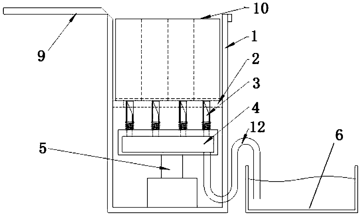
[0025] Such as figure 1 As shown, in this embodiment, a pressure relief device for a pressure spray tank includes an installation structure 1 for installing and limiting a pressure spray tank 10 and a backing plate 2 arranged in the installation structure 1. The installation structure 1 A locking device for locking the pressure spray can 10 is arranged on the top, and a destroying device for destroying the pressure spray can 10 is arranged under the backing plate 2 .
[0026] The pressure spray can 10 to be destroyed is placed inside the structure of the installation structure 1 , and the pressure spray can 10 is locked by a locking device to prevent it from detaching from the installation structure 1 . The pressure spray can 10 is destroyed from the bottom of the pressure spray can 10 by the destruction device. The installation structure 1 and the locking device can effectively limit the pressure spray can 10, avoiding the pressure spray can caused by the pressure air ejectio...
Embodiment 2
[0029] Such as figure 2 As shown, on the basis of the above embodiments, in this embodiment, the destroying device includes several hollow needle tubes 3 and a driving structure for driving the relative movement of the hollow needle tubes 3 and the pressure spray can 10 . Utilizing the hollow needle tube 3 facilitates the pressure spray tank 10 to be punctured, and the residual liquid and high-pressure gas in the pressure spray tank 10 can also be discharged through the through hole in the hollow needle tube 3, which is beneficial to uniformly collect the residue in the pressure spray tank 10, deal with.
[0030] In this embodiment, the driving structure includes a base 4 for installing the hollow needle tube 3 and an air cylinder 5 arranged under the base 4 . The cylinder 5 is used to drive the base 4 to move up and down, thereby driving the hollow needle tube 3 and the pressure spray tank 10 to move relative to each other so that the hollow needle tube 3 punctures the pres...
Embodiment 3
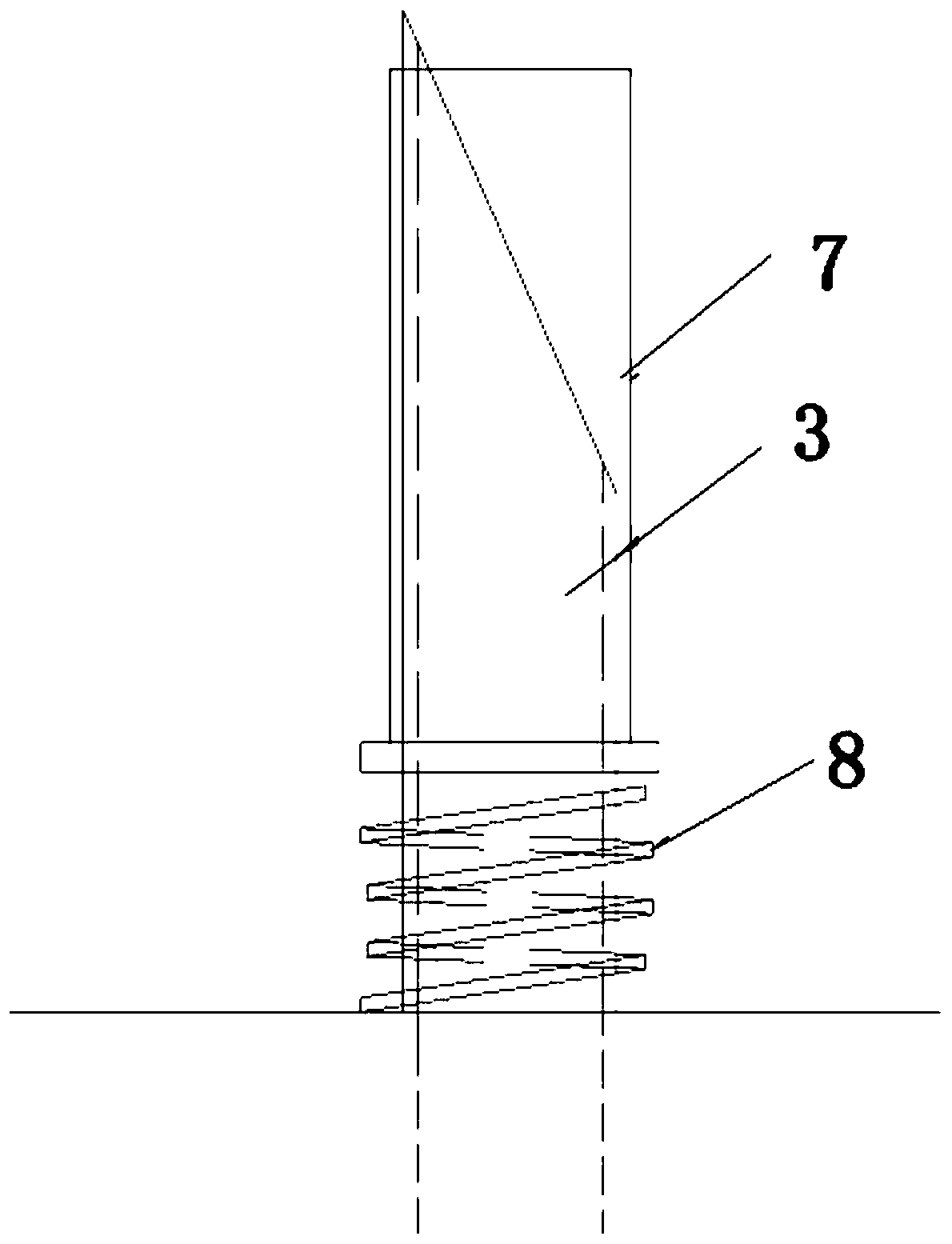
[0034] Such as figure 2 As shown, on the basis of the above-mentioned embodiments, in this embodiment, the base 4 is provided with several protective sleeves 7 set on the hollow needle tube 3, and a spring is arranged between the protective sleeve 7 and the base 4 8. In the process of the hollow needle tube 3 piercing the pressure spray tank 10, the hollow needle tube 3 may be bent under force, and the protective sleeve 7 can limit the bending deformation of the hollow needle tube 3 and increase the rigidity of the hollow needle tube 3, thereby helping to protect the hollow needle tube 3. shape precision. By connecting the protective cover 7 with the base 4 through the spring 8, the protective cover 7 can compress the spring 8 to adaptively adjust the position of the protective cover during the process of the hollow needle tube 3 puncturing the pressure spray tank 10, so as to avoid the protective cover 7 from piercing the pressure spray tank 10. Interfering with the breaki...
PUM
 Abstract
Description
Claims
Application Information
 - R&D
- Intellectual Property
- Life Sciences
- Materials
- Tech Scout
- Unparalleled Data Quality
- Higher Quality Content
- 60% Fewer Hallucinations
Browse by: Latest US Patents, China's latest patents, Technical Efficacy Thesaurus, Application Domain, Technology Topic, Popular Technical Reports.
© 2025 PatSnap. All rights reserved.Legal|Privacy policy|Modern Slavery Act Transparency Statement|Sitemap|About US| Contact US: help@patsnap.com


