
Intelligent deformation detection system for large building steel structure

A detection system and construction steel technology, applied in the testing of machines/structural components, measuring devices, elastic testing, etc., can solve the problems of closed head space, large scale, simulated building obstacles, etc., to prevent vibration from affecting accuracy and prevent Tilting or rollover, the effect of improving detection accuracy

Active Publication Date: 2020-04-28
山东普泰工程检测鉴定有限公司
View PDF11 Cites 5 Cited by
  • Summary
  • Abstract
  • Description
  • Claims
  • Application Information

AI Technical Summary

Problems solved by technology

[0002] Steel structures are widely used in buildings, such as the Great Hall of the People, the National Grand Theater, stadiums and other large buildings. Usually, giant steel trusses are used to support the entire roof. Necessary deformation observations are carried out on such large roof trusses to grasp the deformation laws of the roof truss structure It is of great significance to ensure the safety of buildings; however, the top space of some large historical buildings is airtight, the steel beams are staggered, the scale is large, and the light is not good, which leads to deviations in the detection of building deformation by observation instruments, causing serious consequences
[0003] In order to avoid the occurrence of the above situation, a concept of simulated building appeared, but in the simulated building, due to the variety of structural parts used, it is impossible to truly simulate the stress of various steel structural parts during actual installation. Simulated buildings bring certain obstacles; therefore, an intelligent deformation detection system that can cooperate with detection in real time and accurately measure the deformation of large building steel structures is needed

Method used


Image

  • Intelligent deformation detection system for large building steel structure
  • Intelligent deformation detection system for large building steel structure
  • Intelligent deformation detection system for large building steel structure

Examples


Embodiment Construction

[0031] The following will clearly and completely describe the technical solutions in the embodiments of the present invention with reference to the accompanying drawings in the embodiments of the present invention. Obviously, the described embodiments are only some, not all, embodiments of the present invention.

[0032] In describing the present invention, it should be understood that the terms "upper", "lower", "front", "rear", "left", "right", "top", "bottom", "inner", " The orientation or positional relationship indicated by "outside", etc. is based on the orientation or positional relationship shown in the drawings, and is only for the convenience of describing the present invention and simplifying the description, rather than indicating or implying that the referred device or element must have a specific orientation, so as to Specific orientation configurations and operations, therefore, are not to be construed as limitations on the invention.

[0033] refer to Figure ...


PUM


Abstract

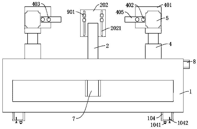
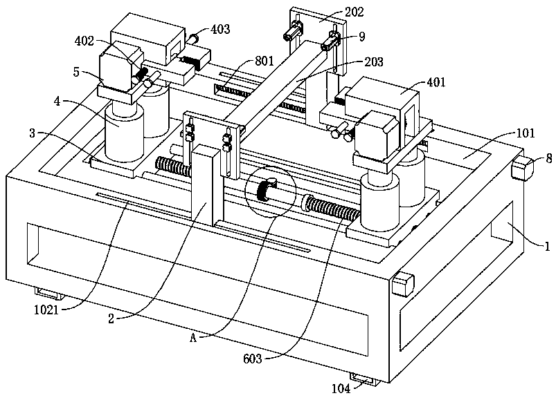
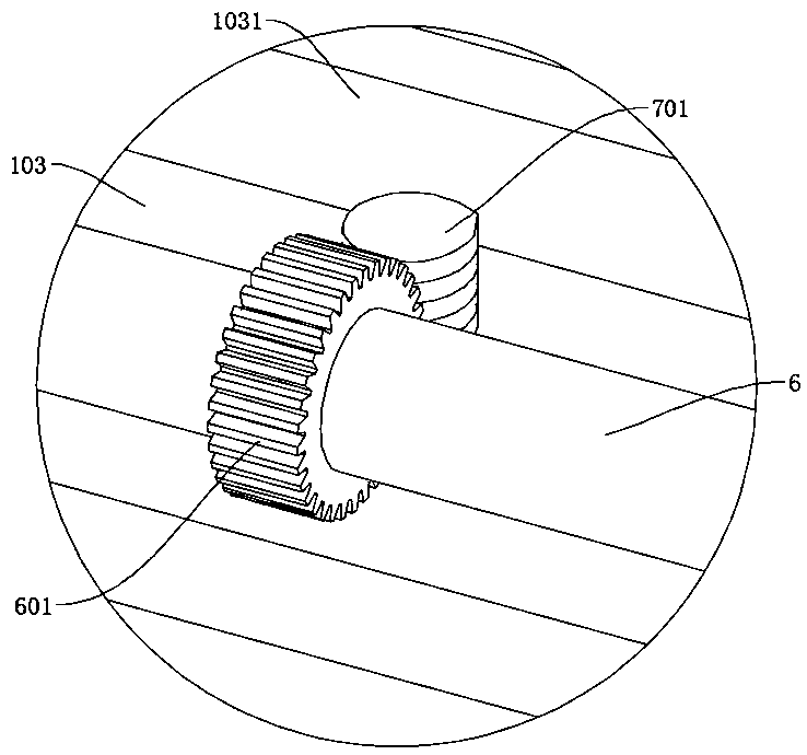
The invention discloses an intelligent deformation detection system for a large building steel structure, and belongs to the technical field of engineering detection. The intelligent deformation detection system for a large building steel structure comprises a pedestal, jacks and precision levels. A first driving rod is rotationally connected into a first sliding groove, mounting bases are in threaded connection with the first driving rod, and a first driving part is connected to the pedestal. Mounting boxes are fixedly connected to the tops of the jacks, second driving rods are rotationally connected to the mounting boxes, clamping blocks are in threaded connection with the two ends of the second driving rods, and second driving parts are connected to the mounting boxes. A second slidinggroove is formed in the side wall of a mounting groove, a third driving rod is rotationally connected into the second sliding groove, a third driving part is connected to the pedestal, a cross rod anda mounting plate are fixedly connected to the top of a supporting rod, and the precision levels are slidably connected to the mounting plate. According to the invention, multidirectional simulation is carried out according to the most real installation stress condition, and the system is suitable for various types of steel structural members, and is high in universality and real in deformation detection.

Description

technical field [0001] The invention relates to the technical field of engineering detection, in particular to an intelligent deformation detection system for large-scale building steel structures. Background technique [0002] Steel structures are widely used in buildings, such as the Great Hall of the People, the National Grand Theater, stadiums and other large buildings. Usually, giant steel trusses are used to support the entire roof. Necessary deformation observations are carried out on such large roof trusses to grasp the deformation laws of the roof truss structure It is of great significance to ensure the safety of buildings; however, the top space of some large historical buildings is closed, the steel beams are staggered, the scale is large, and the light is poor, which leads to deviations in the detection of building deformation by observation instruments, causing serious consequences. [0003] In order to avoid the occurrence of the above situation, a concept of ...

Claims


Application Information

Patent Timeline
Patent Type & Authority Applications(China)
IPC IPC(8): G01M5/00F16M11/42F16M11/04
CPCF16M11/04F16M11/42G01M5/005
Inventor 陈恩震丁鹏高闻尹月酉崔华文
Owner 山东普泰工程检测鉴定有限公司
Learn More