
Drop switch monitoring device

A technology for monitoring devices and drop switches, which is applied in the direction of measuring devices, measuring electricity, and measuring electrical variables, etc., which can solve problems such as unfavorable use, large products, and failure to drop normally, so as to prolong the replacement time, improve stability, and improve accuracy. Effect

Inactive Publication Date: 2020-04-28
江苏紫喻智能科技有限公司
View PDF15 Cites 0 Cited by
  • Summary
  • Abstract
  • Description
  • Claims
  • Application Information

AI Technical Summary

Problems solved by technology

Specifically, when the gravity sensing detection circuit fails, the drop event cannot be sensed when the drop-out fuse falls, or the drop event information cannot be sent, so that the drop-out fuse cannot be monitored normally.
[0004] It is an ideal state for the drop-out fuse to drop when the fuse is blown, but in actual use, due to the quality of the drop-out fuse, improper installation, debris blocking or harsh environment, etc. When the fuse is blown, it will fail to drop normally. In this case, only through switch detection and angle detection, it is impossible to detect that the drop-out fuse is currently in a blown and undropped state, and the maintenance personnel cannot know the fuse in time. A fault occurs, causing the fault to not be handled in time, resulting in a long-term power outage in the relevant area
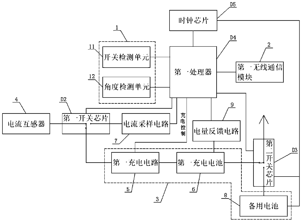
[0005] In addition, when charging and current sampling are required for existing power terminals, two current transformers are generally used to perform charging and sampling work respectively. This terminal needs to be installed on a dropout fuse, and the use of two current transformers will make the product larger , is not conducive to the use of

Method used


Image

  • Drop switch monitoring device
  • Drop switch monitoring device
  • Drop switch monitoring device

Examples


Embodiment Construction

[0041] The present invention will be further illustrated below in conjunction with the accompanying drawings and specific embodiments. This embodiment is implemented on the premise of the technical solution of the present invention. It should be understood that these embodiments are only used to illustrate the present invention and are not intended to limit the scope of the present invention.

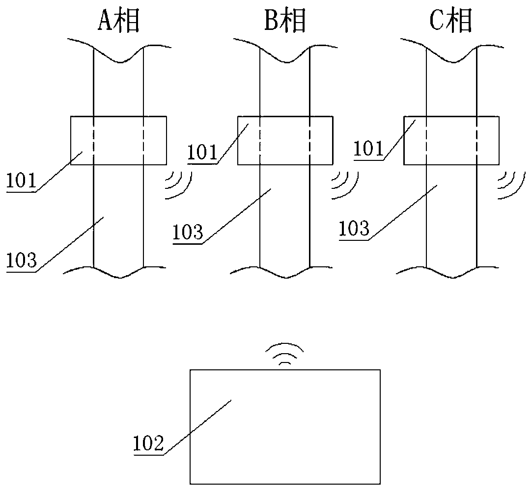
[0042] Such as figure 1 As shown, the embodiment of the present invention provides a drop-out switch monitoring device, including three state monitoring terminals 101 and a collection gateway 102, and the three state monitoring terminals 101 are respectively arranged on three corresponding drop-out fuses of A, B, and C 103, each status monitoring terminal 101 is used to collect the position status and current signal of one phase of the drop-out fuse 103, and the three status monitoring terminals 101 are respectively wirelessly connected to the collection gateway 102 to collect the collec...


PUM


Abstract

The invention discloses a drop switch monitoring device. The device comprises a shape monitoring terminal and a collection gateway. The shape monitoring terminal collects a position and a current signal of a fuse, and the collection gateway judges a working state of the fuse according to the position and the current signal. In the invention, one current transformer is adopted so that current sampling and charging functions are considered; a size of a product is relatively small; two power supply modes of a first rechargeable battery and a standby battery are adopted; power supply and working stability are improved; three detection modes of switch detection, angle detection and current detection are used so as to improve accuracy of judgment; a first processor is awakened to actively detectat regular time through a clock chip so that a situation that the switch detection unit is abnormal and cannot carry out normal monitoring is avoided; whether the switch detection unit and the angledetection unit are abnormal or not can be judged by comparing results of switch detection and angle detection during active detection; and fuse monitoring accuracy is greatly improved, and a service life of the battery can be prolonged.

Description

technical field [0001] The invention relates to the field of electric power monitoring equipment, in particular to a drop switch monitoring device. Background technique [0002] Drop-out fuse has the characteristics of economy, convenient operation, and strong adaptability to outdoor environments. It is widely used in 10kV distribution lines and distribution transformers as components for protection and equipment switching and switching operations. Because there is no traditional monitoring of the drop-out fuse, when the drop-out fuse breaks due to overcurrent, the maintenance personnel cannot know the fuse failure in time, resulting in the failure of the maintenance personnel to deal with the fault in time, resulting in a long-term power outage in the relevant area. [0003] In recent years, some monitoring methods for drop-out fuses have appeared. For example, the invention patent application number: 201620582342.3 discloses a passive auxiliary monitoring system for positi...

Claims


Application Information

Patent Timeline
Patent Type & Authority Applications(China)
IPC IPC(8): G01R31/327
CPCG01R31/3272G01R31/3275
Inventor 王泳李启祥
Owner 江苏紫喻智能科技有限公司
Learn More