Compensation system and method capable of automatically tuning output level of multi-band HFC equipment

An output level, automatic tuning technology, applied in the field of radio frequency transmission, can solve the problem of difficulty in ensuring the level accuracy index, and achieve the effect of solving the frequency band compatibility problem, improving the accuracy, and improving the level accuracy index

Active Publication Date: 2020-04-28
成都芯通软件有限公司
View PDF20 Cites 0 Cited by
  • Summary
  • Abstract
  • Description
  • Claims
  • Application Information

AI Technical Summary

Problems solved by technology

[0003] Another part of the level accuracy deviation comes from the use of different uplink and downlink frequency division methods by network operators, such as 42 / 54MHz, 65 / 87MHz, 85 / 102MHz, 204 / 258MHz, etc., requiring a device to be compatible with multiple frequency bands at the same time. After changing the configuration, the level of the frequency division point will change greatly, and it is difficult to guarantee the level accuracy index

Method used


Image

  • Compensation system and method capable of automatically tuning output level of multi-band HFC equipment
  • Compensation system and method capable of automatically tuning output level of multi-band HFC equipment
  • Compensation system and method capable of automatically tuning output level of multi-band HFC equipment

Examples


Embodiment 1

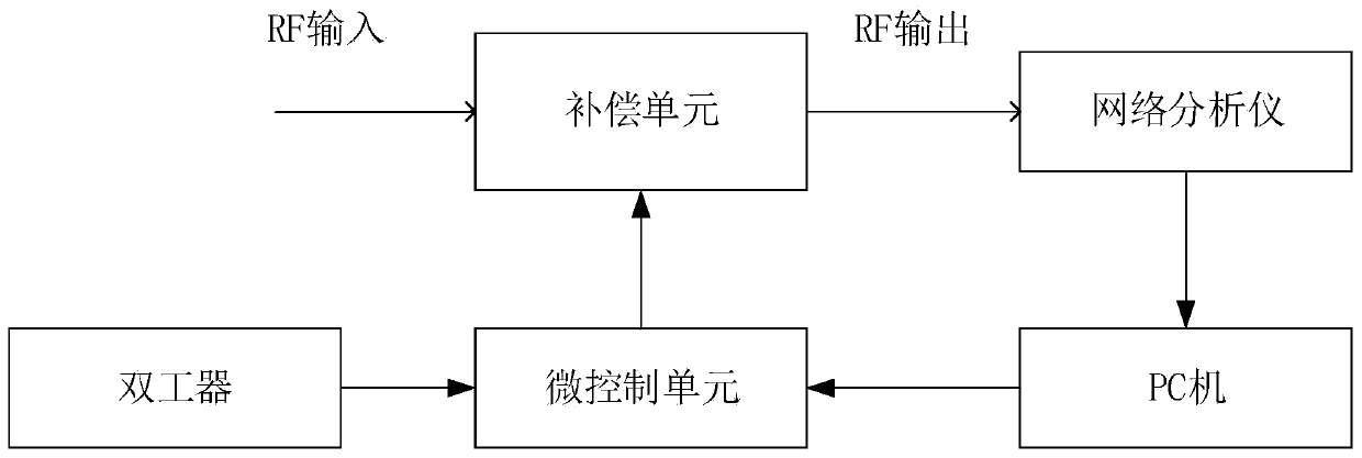
[0037] Such as figure 1 As shown, a multi-band HFC device output level can be automatically tuned compensation system, including a duplexer, a micro-control unit, a compensation unit, a network analyzer and a PC.

[0038] The micro-control unit is connected to the duplexer for obtaining the voltage value on the duplexer; the micro-control unit also receives the configuration data output by the PC, and the micro-control unit according to the voltage value and the configuration data, outputting a control signal to the compensation unit;

[0039] The compensation unit receives the input radio frequency signal, and compensates the input radio frequency signal according to the control signal output by the micro control unit, and outputs the compensated radio frequency signal to the network analyzer;

[0040] The network analyzer receives the compensated radio frequency signal for testing, obtains a test curve, and outputs the test curve to a PC;

[0041] The PC receives the test ...

Embodiment 2

[0049] In this embodiment, on the basis of Embodiment 1, a second compensation circuit is added to the compensation unit, and the compensation unit can receive the first voltage signal output by the micro-control unit, thereby driving the second compensation circuit to work and performing fixed frequency compensation. Point unknown amplitude compensation, and output the compensated radio frequency signal to the network analyzer.

[0050] Such as Figure 4 As shown, the second compensation circuit includes a variable resistance PIN diode D2, a capacitor C2 and an inductor L2, and the variable resistance PIN diode D2, capacitor C2 and inductor L2 are connected in parallel. The second compensation circuit is connected in series with the first compensation circuit, and the positive terminal of the variable resistance PIN diode D2 in the second compensation circuit is connected to the negative terminal of the switching PIN diode D1 in the first compensation circuit.

Embodiment 3

[0052] In this embodiment, on the basis of Embodiment 1, a third compensation circuit is added to the compensation unit, and the compensation unit can receive the second voltage signal and the second control signal output by the micro control unit, thereby driving the third compensation circuit work, perform unknown frequency point and unknown amplitude compensation, output the compensated radio frequency signal and transmit it to the network analyzer.

[0053] Such as Figure 5 As shown, the third compensation circuit includes a variable resistance PIN diode D3, a DTC capacitor C3, and an inductor L3, and the variable resistance PIN diode D3, DTC capacitor C3, and inductor L3 are connected in parallel. The third compensation circuit is connected in series with the first compensation circuit, and the positive terminal of the variable resistance PIN diode D3 in the third compensation circuit is connected to the negative terminal of the switching PIN diode D1 in the first compen...


PUM


Abstract

The invention discloses a compensation system and method capable of automatically tuning the output level of multi-band HFC equipment. The compensation system comprises a duplexer, a micro-control unit, a compensation unit, a network analyzer and a PC. The micro-control unit is connected with the duplexer to obtain a voltage value on the duplexer; the micro-control unit also receives configurationdata output by the PC, and outputs a control signal to the compensation unit according to the voltage value and the configuration data; the compensation unit receives the control signal, compensatesan input radio frequency signal, and outputs the compensated radio frequency signal to the network analyzer; the network analyzer receives the compensated radio frequency signal for testing to obtaina test curve and outputs the test curve to the PC; and the PC receives the test curve and the standard curve, analyzes and compares the test curve and the standard curve to obtain a comparison result,and outputs corresponding configuration data to the micro-control unit according to the comparison result. According to the invention, the output level of the equipment can be automatically tested and debugged, and the output level precision is improved.

Description

technical field [0001] The invention relates to the technical field of radio frequency transmission, in particular to a compensation system and method for automatically tuning output levels of multi-band HFC equipment. Background technique [0002] In the existing broadcast television HFC (Hybrid Fiber-Coaxial, hybrid fiber-coaxial cable network) network, the output level accuracy of radio frequency broadband transmission equipment is highly required. Part of the deviation of level accuracy comes from the uncertainty of devices and cascading between devices, which belongs to the deviation of unknown frequency and amplitude. The traditional method is to manually debug the instrument after testing the output of the equipment by the staff, which has high technical requirements for the staff and low production efficiency. [0003] Another part of the level accuracy deviation comes from the different uplink and downlink frequency division methods used by network operators, such ...

Claims


Application Information

Patent Timeline
Patent Type & Authority Applications(China)
IPC IPC(8): G05B19/042
CPCG05B19/0423G05B2219/21119
Inventor 罗俊
Owner 成都芯通软件有限公司
Why Eureka
Try Eureka