Bridge monitoring method and system based on binocular vision

A binocular vision and bridge technology, applied in image data processing, instruments, character and pattern recognition, etc., can solve the problems of high work intensity, slow measurement, and labor and material resources consumption, so as to improve monitoring efficiency, reduce data processing volume, The effect of improving efficiency

Pending Publication Date: 2020-04-28
武汉纵横天地空间信息技术有限公司
View PDF4 Cites 2 Cited by
  • Summary
  • Abstract
  • Description
  • Claims
  • Application Information

AI Technical Summary

Problems solved by technology

At present, the detection of this danger is mostly in the manual stage, usually using close-range detection equipment or manual detection, and the offset of the bridge is obtained by imprecise measurement or estimation. This method requires the detection personnel to rely on road detection or bridge Manual inspections are carried out regularly with equipment, which requires high work intensity, high inspection costs, and high requirements for personnel safety; and although the bridge part is found to be within the specified offset range during manual inspections, after a period of time, the offset The

Method used


Image

  • Bridge monitoring method and system based on binocular vision
  • Bridge monitoring method and system based on binocular vision
  • Bridge monitoring method and system based on binocular vision

Examples


Embodiment Construction

[0052] The principles and features of the present invention are described below in conjunction with the accompanying drawings, and the examples given are only used to explain the present invention, and are not intended to limit the scope of the present invention.

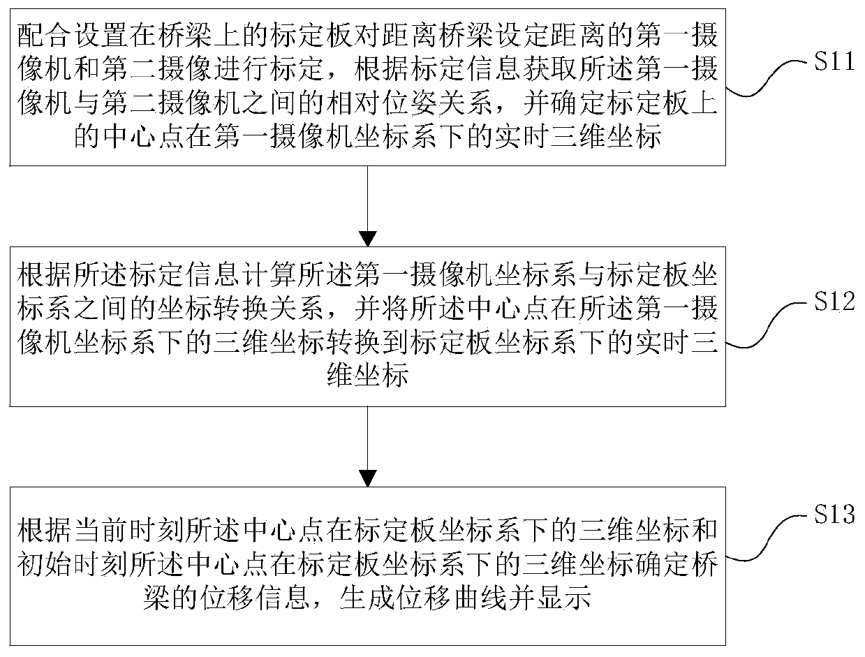
[0053] Such as figure 1 As shown, a bridge monitoring method based on binocular vision includes the following steps:

[0054] S11: Cooperate with the calibration board installed on the bridge to calibrate the first camera and the second camera at a set distance from the bridge, obtain the relative pose relationship between the first camera and the second camera according to the calibration information, and determine The real-time three-dimensional coordinates of the center point on the calibration plate under the first camera coordinate system;

[0055] S12: Calculate the coordinate transformation relationship between the first camera coordinate system and the calibration plate coordinate system according to the ca...


PUM


Abstract

The invention relates to a bridge monitoring method and system based on binocular vision, and the method comprises: calibrating a first camera and a second camera, obtaining the relative pose relationbetween the two cameras, and determining the real-time three-dimensional coordinates of a central point on a calibration plate under a first camera coordinate system; calculating a coordinate conversion relationship between the first camera coordinate system and the calibration plate coordinate system according to the calibration information, and converting a three-dimensional coordinate of the central point under the first camera coordinate system into a real-time three-dimensional coordinate under the calibration plate coordinate system; and determining the displacement information of the bridge by combining the three-dimensional coordinates of the central point at the initial moment under the calibration plate coordinate system. By calibrating the relative pose relationship between thetwo cameras, the three-dimensional coordinate of the center point of the calibration plate under the first camera coordinate system is converted to be under the coordinate system of the calibration plate, and the displacement information of the bridge is determined by combining the coordinates of the center point of the initial moment under the coordinate system of the calibration plate; and manual measurement is replaced, and the method is high in precision, high in efficiency and low in price.

Description

technical field [0001] The invention relates to the technical field of bridge monitoring, in particular to a binocular vision-based bridge monitoring method and system. Background technique [0002] At present, most bridge monitoring systems use manual measurement to measure the displacement of the bridge at long intervals. This method is slow in measurement, cannot monitor bridge displacement in real time, and cannot measure multiple points at the same time. [0003] Concrete is the most widely used building material in building frames. The research and application practice of modern science on concrete shows that in bridges with concrete material structures, due to thermal expansion and contraction and external forces acting on the bridge, the deviation of the bridge is unavoidable. At present, the detection of this danger is mostly in the manual stage, usually using close-range detection equipment or manual detection, and the offset of the bridge is obtained by imprecise...

Claims


Application Information

Patent Timeline
IPC IPC(8): G06K9/00G06T7/70
CPCG06T7/70G06V20/10
Inventor 王五丰陈磊钟小军廖水华程曦李成建王杰朱淑娟孙荣康阎首宏
Owner 武汉纵横天地空间信息技术有限公司
Why Eureka
Try Eureka